All-Terrain Autonomous Navigation Robot with GPS-IMU Jaguar 4x4 Wheel User Guide Copyright © 2014, Dr Robot Inc. All Rights Reserved. www.DrRobot.com V20.12.
WARNINGS Do NOT power on the robot before reading and fully understanding the operation procedures explained in this manual. Always charge the battery when battery is running low or before storage. Always turn your robot off when not in use. Over-draining the battery (such as keeping the robot on without charging) will damage the battery. Never position your finger(s) in between the track and/or arm’s moving parts even when the power is off.
Copyright Statement This manual or any portion of it may not be copied or duplicated without the expressed written consent of Dr Robot. All the software, firmware, hardware and product design accompanying with Dr Robot’s product are solely owned and copyrighted by Dr Robot. End users are authorized to use for personal research and educational use only.
Table of Contents I. II. III. IV. V.
I. Specifications Jaguar-4x4-wheel Mobile Robotic Platform is designed for indoor and outdoor operation requiring higher ground clearance and faster maneuverability. Jaguar-4x4-wheel platform is a wheeled version of the Jaguar-Lite platform. Jaguar-4x4-wheel is driven by four powerful (80W) motors, one for each wheel. Jaguar-4x4-wheel platform is rugged, light weight (< 20Kg), fast (max 11km/hr), with high ground clearance (88mm), compact, weather and water resistant.
Shock resistant chassis Drop to concrete: Max: 1200mm (4ft) Rated: 900mm (3ft) Motion and sensing controller (PWM, Position and Speed Control) 5Hz GPS and 9 DOF IMU (Gyro/Accelerometer/Compass) Laser scanner (4m or 30m) (Optional) Temperature sensing & Voltage monitoring Headlights Color Camera (640x480, 30fps) with audio WiFi802.11G (Optional WiFi 802.
Jaguar Core Components JAGUAR4x4W-ME Jaguar 4x4 Wheel Chassis (including motors and encoders) 1 PMS5005-J4W Motion and Sensing Controller (Jaguar 4x4 Wheel Version) 1 WFS802G WiFi 802.11b/g Wireless Module 1 DMD1200 12A (peak 25A) Dual-channel DC Motor Driver Module 2 PMCHR12 DC-DC Power Board 1 AXCAM-A 640x480 Networked Color Camera (max.
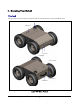
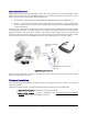
II. Knowing Your Robot Overlook The figure below illustrates the key components that you will identify on the Jaguar-4x4-Wheel robot. GPS Batteries Camera Headlights Power Switch Start Button Handle Bar Jaguar-4x4-Wheel Platform Copyright © 2014, Dr Robot Inc. All Rights Reserved. www.DrRobot.com -8- V20.12.
Operation Scenario Diagram below illustrates the typical operation scenario. The Jaguar-4x4-wheel is a wireless networked outdoor mobile robot. It comes with a wireless 802.11 AP/router. The remote host controller PC running the “Jaguar Control” program connects to the Jaguar-4x4-wheel robot via: Network cable – Connect the robot on-board AP/router.
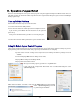
III. Operation of Jaguar Robot End user could develop his own Jaguar control program using the supplied development API and tools. Here, we will show you how to control the robot using the included “Jaguar Control Program” (You need to install Google Earth program first). Turn on/off the Platform Please follow the below steps to turn on the robot. 1. Turn the main switch to "ON" position. 2. Press the start button for a while (around 1 second) then release.
Google Earth is then loaded (this may take a while). Google Earth supports offline use (without Internet), but you have to obtain the map online ahead of use. When Internet is not presented, this loading process will take a longer time when trying to connect with Google Earth website. You will not get the correct Latitude and Longitude position by clicking on map before the map loading is finished. When loaded, click “OK” button.
You could use the vertical track bar to zoom in or out. When the GPS-IMU module is presented, this program will connect and display the GPS information on Google Earth and IMU raw data on the 6 chart boxes. When camera is presented, the video and AV control buttons will be shown in the video window. You could use the included Gamepad controller to navigate the robot.
When is clicked, it will display laser scanner data in polar view as shown below. Yellow: Driving Direction (Modified by sensor map) Blue: Gamepad Driving Direction Polar Sensor Map Enable Collision Avoidance * When the "CA" checkbox is checked, the program will limit the maximum output PWM to 65% full power. Battery information and motor information is displayed here. If the robot uses the included Li-Po battery, you need to stop the robot when voltage is below marked voltage (22.
data by right-clicking on “Temporary Places”, then choosing “Delete Contents”. (That is why we did not hide Google Earth program) On normal program exit, Google Earth will be closed. However, you should double check using “Windows Task Manager”; otherwise, you may not be able to display Google Earth when you start Jaguar control program again. Recharging Jaguar robot uses high performance LiPo batteries. Extreme caution is needed when dealing with this type of battery, explosion and damage could occur.
6) Press button for few seconds, the charge station will check the battery and display what the reading is. It should be same as your settings above. 7) If everything is right, you can press button again to start charging. to switch the display to show the battery status. The display 8) Press should show each battery reading as below image.
In this program, you could use open loop PWM control(by clicking “PWM Control Go” button), velocity Control(by clicking “Velocity Control Go” button) and position control (by clicking “Distance Control Go” button). You also could adjust the default velocity control PID and position control PID parameters. All default value are displayed on the program GUI. IV. Hardware and Electronics Network Settings Wireless Router Setting The included pre-configured wireless 802.
Device Default Network Settings Note: The Ethernet modules are configured to serial-to-Ethernet mode in Jaguar platform. Ethernet Module 1 192.168.0.60 Port 1 Port Number 10001, UDP 115200. 8, N, 1, no flow control Port 2 Port Number 10002, TCP 19200. 8, N, 1, no flow control Ethernet Module 2 192.168.0.61 Port 1 Port Number 10001, TCP 57600. 8, N, 1, no flow control Port 2 Port Number 10002, TCP 115200. 8, N, 1, no flow control Camera 192.168.0.
Charging Plug Antenna Right Front Motor Right Rear Motor LiPo 22.2V 10AH Left Front Motor Left Rear Motor OFF Host Control PC ON Main Switch Motor Driver Board #1 Motor Driver Board #1 Gamepad Controller 5V Head Lights 9 DOF IMU (Gyro/ Accelerometer/Compass) Power 5V GPS Module Power 5V 3.3V Camera (AV) Power 5V = Copyright © 2014, Dr Robot Inc. All Rights Reserved. www.DrRobot.com - 18 - V20.12.14 Antenna 5V Power 5V Wireless AP/Router Power 5V LAN 5V Ethernet Module 2 Power 3.
Motor Driver Board The left front and left rear motors are connected to the 1st channel on the motor driver board while the right front and right rear motors are connected to the 2nd channel. Input power Max current Input voltage H-Bridge 2 channels up to 25A continuous power per channel, peak up to 50A per channel for a few seconds 6~24V, 30V absolute max Motion and Sensing Controller This is a special version of PMS5005 board.
Gyro Sensors ITG3200 Triple-Axis digital output gyro sensor Accelerometers 3 Axis ADXL345 13bit resolution Max +/-16G 3 Axis HMC5883L magnetometer 50Hz Output all sensors raw AD data, magnetic sensor will be measured every 220ms Magnetic Compass Output Frequency Laser Scanner Two laser scanner options are available, one with measurement range of 0.02-4m, and other one is 0.1-30m. Input power Detectable range Accuracy Measurement Resolution Angular Resolution Scanning angle 5V 0.02-4m 0.
V. Further Development & Programming The Jaguar Control program The Jaguar Control program is written with Visual Studio 2008 express (in C#) under .Net 3.5 framework. You could download the development tools (Visual Studio 2008 express under .Net 3.5 framework) free from Microsoft. Please refer to the “Dr Robot Application Development Notes on C# Programming for Robot Control” for further information.
You could read board voltage(5V) and battery voltage in standard sensor Event. private void myJaguar_StandardSensorEvent(object sender, EventArgs e) { boardVol = ((double) myJaguar.GetSensorBatteryAD1() / 4095 * 9); motVol = ((double) myJaguar.GetSensorBatteryAD2() / 4095 * 34.498); } You could read motor temperature sensor in custom sensor event, function Trans2Temperature() is based on the sensor specification to translate AD value to temperature (in celcius degree).
To turn left with full power myJaguar.DcMotorPwmNonTimeCtrAll(0,0,NOCONTROL,0,0,NOCONTROL); To turn right with full power myJaguar.DcMotorPwmNonTimeCtrAll(32767,32767,NOCONTROL,32767,32767,NOCO NTROL); For encoder speed/position control of each motor, you could referee “DrRobot Jaguar4X4 Motor Control Demo” program and you could find the source code in the installation folder. To control head lights, using expanded IO port bit7. Turn off light: Turn on light: myJaguar.
Camera with Two Way Audio You need to install the camera ActiveX control on your system by running the “AXISMediaControlSDK.exe”. You could find some sample codes (C++, C#, VB) in C:\Program Files\Axis Communications\AXIS Media Control SDK\samples and the corresponding SDK documents in C:\Program Files\Axis Communications\AXIS Media Control SDK\doc.