INSTALLATIEHANDLEIDING EN GEBRUIKERSHANDLEIDING (NL/BE) INSTALLATION MANUAL AND USER MANUAL (GB/IE) GLOBAL 70 GLOBAL 70 XT G20/G25 Lees en bewaar dit document zorgvuldig Read this document and store it carefully DRU VERWARMING B.V. HOLLAND 957.637.
INSTALLATIEHANDLEIDING Woord vooraf ................................................................................2 1. Inleiding ..................................................................................2 2. CE verklaring .......................................................................2 3. Veiligheid 3.1 Algemeen ..................................................................................2 3.2 Voorschriften ...........................................................................
INSTALLATIEHANDLEIDING Dit systeem kan zowel door de gevel als door het dak worden aangebracht. Deze toestellen worden ingebouwd in een boezem. Voor een goede afvoer van de warmte moet de boezem geventileerd worden. DRU kan verschillende ventilatieelementen leveren. De toestellen worden geleverd met een draadloze afstandsbediening; deze werkt op batterijen.
INSTALLATIEHANDLEIDING • voorkom dat de ontstekingskabel in contact komt met andere bedrading; • vermijd dat de ontstekingskabel langs metalen delen ligt om verzwakking van de vonk te voorkomen; • werk de randen bij strakke inbouw goed af; • stuc niet op of over de flenzen; • voorkom beschadiging van de ruit bij het verwijderen/ plaatsen; • maak de ruit schoon vóór ingebruikname ter voorkoming van inbranden van vuil; • zorg ervoor dat de draden van thermokoppel 2 vrij liggen van delen die warm worden.
INSTALLATIEHANDLEIDING Let op - Ø160 mm voor een geveldoorvoer door onbrandbaar materiaal; - Ø 250 mm voor een geveldoorvoer door brandbaar materiaal; - Ø160 mm voor een dakdoorvoer door onbrandbaar materiaal; - Ø 250 mm voor een dakdoorvoer door brandbaar materiaal. • Zet het toestel op de bestemde plek. Controleer of het toestel geschikt is voor de gassoort en gasdruk ter plaatse. 6.3 Gasaansluiting In de gasaansluiting dient een gaskraan geplaatst te worden in de omgeving van het toestel.
INSTALLATIEHANDLEIDING Verbrandingsgasafvoer- / verbrandingsluchttoevoersysteem 6.5.1 Algemeen Het toestel is van het type C11/C31. Het toestel wordt aangesloten op een gecombineerd verbrandingsgasafvoer-/verbrandingsluchttoevoersysteem, hierna te noemen het concentrische systeem. De doorvoer naar buiten kan zowel met een geveldoorvoer (zie paragraaf 6.5.2) als met een dakdoorvoer (zie hiervoor paragraaf 6.5.3) worden uitgevoerd.
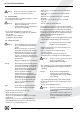
INSTALLATIEHANDLEIDING !Let op - Zorg ervoor dat de juiste insteeklengte behouden blijft; - Plaats de geveldoorvoer met de ril/ felsnaad aan de bovenkant; - Plaats de horizontale concentrische pijpstukken onder afschot naar de geveldoorvoer ter voorkoming van inwaterend regenwater. Voorbeelden Ter verduidelijking worden 2 voorbeelden gegeven om de toelaatbaarheid van een concentrisch systeem en de voorwaarden voor het afstellen van het toestel te bepalen.
INSTALLATIEHANDLEIDING G20/25 Totale aantal meters verticale en/of schuine pijplengte Totale aantal meters horizontale pijplengte 1 2 3 4 5 6 7 Ļ8 Ļ9 10 11 12 geen bochten 0 B B B C C C C C D D D D 2 bochten 0 A A B B B C C C C C D D A A B B B C C C C C A A B B B C C C A A B B B C A A B B 1 2 ĺ 3 4 5 3 bochten 0 A 1 A A B B B C C C C C A A A B B B C C C C A A A B B B C C A A A B B B A A A B 2
INSTALLATIEHANDLEIDING - Gebruik hittebestendig isolatiemateriaal bij doorvoer door brandbaar materiaal. !Let op Let op Sommige hittebestendige isolatiematerialen bevatten vluchtige componenten, die langdurig een onaangename geur verspreiden; deze zijn niet geschikt. Plaats het concentrische systeem als volgt: • Bouw het systeem op vanaf (de aansluitstomp van) het toestel. • Sluit de concentrische pijpstukken en zonodig de bochten aan.
INSTALLATIEHANDLEIDING 6.8.1 Restrictieschuif (R) De restrictieschuif (R) is los meegeleverd. Deze wordt als volgt geplaatst (zie Afb. 6): • Plaats de restrictieschuif. • Stel de afstand van de restrictie in met de bijgeleverde mal (zie Afb. 7). • Zet de restrictieschuif vast m.b.v. de parker (U). Ga als volgt te werk bij het plaatsen van het bedieningskastje; zie Afb. 4 voor details: • Maak in de boezem een opening van 285 x 194 mm (h x b). • Plaats het binnenframe (1); draai hiervoor bouten (5) los.
INSTALLATIEHANDLEIDING !Let op Maak gebruik van de plaatsingsbeugels zoals weergegeven is in de afbeeldingen. In de Gebruikershandleiding, hoofdstuk 4, Draadloze afstandsbediening, is de bediening van het toestel inclusief de werking van de afstandsbediening beschreven. • Vul de bak rondom de brander met chips; verdeel de chips gelijkmatig; zie Afb. 13j. • Plaats tenslotte stam D, de linker stam; zie Afb. 13k. Let op 6.10.
INSTALLATIEHANDLEIDING !Let op - De waakvlam mag niet lager ingesteld worden met behulp van de instelmogelijkheid op het gasregelblok. 8.3.1 Waakvlam • Controleer de ontsteking van de waakvlam: - de waakvlambrander dient bij de eerste poging te starten. Als de waakvlam niet brandt, dan • Controleer of de ontsteking vonkt: a) Zo nee, dan ligt ontstekingskabel waarschijnlijk niet vrij van metalen delen; b) Zo ja, dan zit er waarschijnlijk lucht in de leiding.
INSTALLATIEHANDLEIDING !Let op Als de boezem gemaakt is van steenachtige materialen of afgewerkt is met stucwerk mag dit pas 6 weken na het plaatsen van de boezem ter voorkoming van krimpscheuren. • Inspecteer het verbrandingsgasafvoer- / verbrandingsluchttoevoersysteem. Let op • Controleer of het vlambeeld acceptabel is.
INSTALLATIEHANDLEIDING In de onderstaande tabel vindt u een overzicht van storingen die kunnen optreden, de mogelijke oorzaak en de oplossing. Tabel 4: Diagnose van storingen PROBLEEM A. Geen transmissie (motor draait niet) MOGELIJKE OORZAAK 1. De (nieuwe) communicatie code tussen ontvanger en afstandsbediening moet nog bevestigd worden. 2. Lege batterijen. 3. Ontvanger beschadigd. 4. Afstandsbediening beschadigd. 5. Motorkabel bij de klep / ontvanger gebroken. 6.
INSTALLATIEHANDLEIDING PROBLEEM E. Geen waakvlam MOGELIJKE OORZAAK OPLOSSING 3. Kromme pennen van de 8-draads connector. 4. Magneetklep beschadigd. 5. Thermokoppel 2 nog te warm. 3. Zorg dat de pennen van de 8-draads connector recht staan. 4. Vervang het gasregelblok. 5. Wacht tot het thermokoppel voldoende is afgekoeld 1. Lucht in de waakvlamleiding. 1. Spoel de leiding of start het ontstekingsproces meerdere keren. 2. Controleer de polariteit van de thermokoppelbedrading.
INSTALLATIEHANDLEIDING MOGELIJKE OORZAAK OPLOSSING H. Er zijn wel korte geluidssignalen maar geen vonken en er is geen geluid / getik hoorbaar van de magneet die de klep opent 1. Batterijen (bijna) leeg. 1. Vervang de batterijen in de ontvanger. !Let op Voorkom kortsluiting tussen de batterijen en metalen delen van het toestel. I. Waakvlam brandt maar er is geen gasstroom naar de hoofdbrander 1. Knop A in MAN stand. 1. Draai knop A op gasregelblok naar ON; zie Afb. 16. 2.
INSTALLATIEHANDLEIDING Bijlage 1 Meegeleverde onderdelen In de onderstaande tabel staan de onderdelen vermeld die met het toestel worden meegeleverd. Tabel 5: Meegeleverde onderdelen Onderdeel Aantal Houtset 1x Bedieningskastje Optioneel Handleiding bedieningskastje Optioneel Boekje met handleidingen 1x Sierstrip links 1x Sierstrip rechts 1x Afstelmal voor restrictieschuif 1x Restrictieschuif 1x Reserveparkers t.b.v.
GEBRUIKERSHANDLEIDING Woord vooraf ..............................................................................18 1. Inleiding ................................................................................18 2. Veiligheid ..............................................................................18 2.1 Algemeen ................................................................................18 2.2 Voorzorgsmaatregelen / veiligheidsinstructies ...............18 3. Ingebruikname .......................
GEBRUIKERSHANDLEIDING Woord vooraf 2. Veiligheid Als fabrikant van gasverwarmingstoestellen ontwikkelt en produceert DRU producten volgens de hoogst mogelijke kwaliteits-, prestatie- en veiligheidseisen. U kunt hierdoor rekenen op jarenlang gebruiksplezier. Dit toestel is voorzien van een CE merk. Gastoestellen die voldoen aan de eisen voor veiligheid, milieu en energiegebruik, de zogenaamde essentiële eisen, uit de Europese Gastoestellenrichtlijn hebben het recht het CE-merk te dragen.
GEBRUIKERSHANDLEIDING !Tip - Huisdieren en vooral vogels kunnen gevoelig zijn voor de vrijkomende dampen; - Het vlambeeld wordt in het begin beïnvloed door het uitdampen van vluchtige componenten. 4.1 Ontvanger De ontvanger bevindt zich in het bedieningskastje (zie Afb. 1) antenne kabels t.b.v. thermokoppel - Zet het toestel in de hoogste stand om het uitdampen te versnellen; - Ventileer de ruimte goed; - Verwijder huisdieren uit de ruimte. knop B 3.
GEBRUIKERSHANDLEIDING matige regeling van de afstandsbediening (zie Afb. 2). dezelfde code gebruiken en de werking van uw toestel beïnvloeden. 3 Ga als volgt te werk: • Druk de reset-knop op de ontvanger in totdat u achtereenvolgens twee geluidssignalen hoort (zie Afb. 3). • Laat na het tweede, langere signaal de reset-knop los.
GEBRUIKERSHANDLEIDING • Druk op de knop (kleine vlam) om de vlamhoogte te verlagen en/of het toestel in de stand-by stand te zetten. • Druk op de knop (grote vlam) om de vlamhoogte te verhogen en/of de hoofdbrander in te schakelen vanuit de stand-by (waakvlam) stand. Let op 4 4.2.2.3 Uitschakelen Het toestel wordt uitgeschakeld door op de knop OFF te drukken. Ook de waakvlam gaat dan uit.
GEBRUIKERSHANDLEIDING !Let op - Leg de afstandsbediening steeds op dezelfde plek, zodat de thermostaat de omgevingstemperatuur ’voelt’; - Zorg dat deze plek vrij is van invloeden als tocht, warmte van radiatoren en rechtstreeks zonlicht. Voorbeeld schakeltijden U hebt een dagtemperatuur resp. nachttemperatuur ingesteld van b.v. 20 ºC en 15 ºC. P1 ✹ TIMER = 7 uur; de temperatuur gaat om 7 uur naar 20 ºC. P1 TIMER = 9 uur; de temperatuur gaat om 9 uur naar 15 ºC.
GEBRUIKERSHANDLEIDING N e d e r l a n d s 5. Onderhoud Het toestel dient minimaal één keer per jaar op zijn goede en veilige werking gecontroleerd te worden. Let op !Let op - Laat het onderhoud van uw toestel uitsluitend uitvoeren door een vakbekwame installateur op het gebied van gas sfeerverwarming; - Laat een gescheurde of gebroken ruit meteen vervangen; - Breng zelf geen wijzigingen aan het toestel aan.
24
INSTALLATION MANUAL Preface .........................................................................................26 1. Introduction........................................................................26 2. CE declaration...................................................................26 3. SAFETY ................................................................................26 3.1 General....................................................................................26 3.2 Regulations .......
INSTALLATION MANUAL This system can be installed through the wall or through the roof. These appliances are built within a chimney breast. In order to reach a proper heat discharge, the chimney breast must be ventilated. DRU is able to supply various ventilation elements. The appliances are supplied with a wireless remote control that works on batteries.
INSTALLATION MANUAL • avoid that the ignition cable touches or crosses the antenna; • make sure the ignition cable cannot come into contact with other wires; • avoid that the ignition cable runs alongside metal parts, in order to prevent weakening of the spark; • properly finish the edges in case of a tight construction; • do not apply plaster on or over the flanges; • avoid damages when removing/placing the pane; • clean the pane before you use the appliance, in order to prevent dirt from burning in the g
INSTALLATION MANUAL 6.3 Gas connection Place a gas tap in the gas connection, close to the appliance. - Ø160 mm for a roof terminal through non combustible material; - Ø 250 mm for a roof terminal through combustible material. • Place the appliance on its destined location. Caution - Make sure there is no dirt in gas pipes and connections; - Prevent twisting the gas tap when connecting the gas pipe. The gas control is mounted under the appliance, at the burner plate.
INSTALLATION MANUAL 6.5.2.2 Placing concentric system with wall terminal Caution If necessary, you can also use an existing chimney (see section 6.5.4). Caution - Only use the concentric system supplied by DRU (Ø100 / Ø150 mm). This system has been tested together with the appliance. DRU cannot guarantee a proper and safe operation of other systems and does not accept any liability for this; - For connecting to an existing chimney you should only use the chimney kit supplied by DRU.
INSTALLATION MANUAL !Caution - Make sure that the right insertion length is maintained; - Place the wall terminal with the groove/ folded seam at the top; - Make sure the horizontal concentric pipe pieces are sloping towards the wall terminal, in order to prevent rain water from entering. Examples To clarify, we will give 2 examples to determine the allowability of a concentric system and the conditions for setting the appliance. In Table 2 the route to be followed is indicated by arrows.
INSTALLATION MANUAL G20/G25 Total number of meters horizontal pipe length Total number of meters vertical and/or sloping pipe length 1 2 3 4 5 6 7 Ļ8 Ļ9 10 11 12 no bends 0 B B B C C C C C D D D D 2 bends 0 A A B B B C C C C C D D A A B B B C C C C C A A B B B C C C A A B B B C A A B B 1 2 ĺ 3 4 5 3 bends 0 A 1 A A B B B C C C C C A A A B B B C C C C A A A B B B C C A A A B B B A A A B 2 3 ĺ 4
INSTALLATION MANUAL !Caution Some heat-resistant insulation materials contain volatile components that will spread an unpleasant smell for a prolonged time; these are not suitable.
INSTALLATION MANUAL 6.8.1 Baffle (R) The baffle (R) is supplied separately. This is mounted as follows (see fig. 6): • Place the baffle. • Use the template supplied to set the distance of the restriction (see fig. 7). • Fix the baffle by using the self-tapping screw (U). Proceed as follows, when placing the control box; see fig. 4 for details: • Make an opening in the chimney breast of 285 x 194 mm (h x w). • Place the inner frame (1); unscrew bolts (5) for this. !Tip 6.8.
INSTALLATION MANUAL !Caution Use the placement brackets as indicated in the figures. User Manual, chapter 4, Wireless Remote Control, describes the operation of the appliance including the way the remote control works. • Fill the tray surrounding the burner with chips; equally spread the chips; see fig. 13j. • Finally place log D, the left log; see fig. 13k. Caution 6.10. Pane After placing the wood set you can place the pane, as described below.
INSTALLATION MANUAL !Caution 8.3.1 Pilot burner • Check the ignition of the pilot burner: - the pilot burner should start at the first attempt. If the pilot burner does not ignite: • check if the ignition sparks: a) If not, the ignition cable is probably not lying free from metal parts; b) If it does, there is probably still air in the pipe. • Bleed the pipe and/or • Lay the ignition cable free from metal parts.
INSTALLATION MANUAL !Caution If the chimney breast is made of stonelike materials or has a plaster finish, this may only take place 6 weeks after placing the chimney breast, in order to prevent shrinkage cracks. • Inspect the flue gas discharge / combustion air supply system. Caution You must always perform a final check. • Perform a check as described in chapter 8. • Check whether the flame image is acceptable.
INSTALLATION MANUAL In the following table you will find an overview of malfunctions that might occur, the possible causes and the remedies. Table 4: Diagnosis of malfunctions PROBLEM A. No transmission (motor will not run) POSSIBLE CAUSE 1. The (new) communication code between receiver and remote control must still be confirmed. 2. Empty batteries. 3. Receiver is damaged. 4. Remote control is damaged. 5. Motor cable at valve/receiver is broken. 6. Bent pins of the 8-wire connector. 7.
INSTALLATION MANUAL PROBLEM POSSIBLE CAUSE 3. Bent pins of the 8-wire connector. 4. Damaged magnetic valve. 5. Thermocouple 2 still too hot. E. No pilot burner flame 1. Air in the pilot burner pipe. 2. Wires of thermocouple 1 have been cross-connected. 3. No spark at the pilot burner. 4. Injector is blocked up. REMEDY 3. Make sure that the pins of the 8-wire connector are straight. 4. Replace the gas control. 5. Wait until the thermocouple has cooled down sufficiently 1.
INSTALLATION MANUAL POSSIBLE CAUSE REMEDY H.There are short sound signals, but no sparks and no sound / clicks can be heard of the magnet opening the valve 1. Batteries (almost) empty. 1. Replace the receiver’s batteries. !Caution Avoid short circuit between the batteries and metal parts of the appliance. I. Pilot burner is burning, but there is no gas flow to the main burner 1. Button A in position MAN. 1. Turn button A on the gas control to ON; see fig. 16. 2.
INSTALLATION MANUAL Appendix 1 Parts included with the delivery In the following table you can find the parts that are supplied with the appliance.
USER MANUAL Preface .........................................................................................42 1. Introduction........................................................................42 2. SAFETY ................................................................................42 2.1 General....................................................................................42 2.2 Precautions / safety instructions........................................42 3. Taking the appliance in operation..
USER MANUAL Preface 2. Safety DRU, a manufacturer of gas-fired heating appliances, develops and produces products that comply with the highest quality, performance and safety requirements. This will enable you to enjoy using this product for many years to come. The appliance is provided with a CE mark.
USER MANUAL !Tip - Pets and birds in particular can be sensitive to the vapours that are released; - In the beginning the flame image is affected by the evaporation of volatile components. 4.1 Receiver The receiver is located in the control box (see fig. 1). antenna thermocouple wiring - Set the appliance to its highest level to speed up the evaporation process; - Keep the room well ventilated; - Remove pets from the room. 3.
USER MANUAL manual control of the remote control (see fig. 2). 3 Follow the procedure described below: • Hold down the reset button on the receiver, until you hear two consecutive sound signals (see fig. 3). • After the second, longer signal, let go of the reset button. • Press button (small flame) or button (large flame) on the remote control within 20 seconds, until you hear an extra long sound signal: this is the confirmation of a correct communication.
USER MANUAL Caution - If you continue to press down button (large flame) on the remote control, the main burner should be largely ignited within about 10 seconds. If this is not the case, you must close the gas tap and warn your installer; - If the appliance ignites with a pop sound, you must close the gas tap and contact your installer. Ignite the appliance as follows: • Set button A on the gas control to ON (button B is controlled automatically) (see fig. 4).
USER MANUAL 4.2.5.1 Setting day/night temperature By using the SET button, you will go through the following functions: MAN ✹ TEMP TEMP (P*) TIMER MAN 4.2.6.1 Setting times for the timer To set the timer, proceed as follows: • Set the day and night temperature as described above at section 4.2.5.1. • Briefly press the SET button to enter the (P*) TIMER position. • Press the SET button until P1 ✹ TIMER is displayed and the time flashes.
USER MANUAL As user, you are only allowed to clean the appliance on the outside: - Do not use corrosive detergents; - Paint damages, resulting from objects fallen/placed against the mantel of the appliance are not covered by the warranty. E n g l i s h !Caution 6. Environment 6.1 General Packaging materials must be disposed off in accordance with the regulations. Batteries are considered as small chemical waste and should be placed in special containers. 6.
Bijlage 3 Afbeeldingen / Appendix 3 Figures 150 100 150 100 724 754 720 604 min 840 max 890 454 min 690 max 740 50 50 724 754 720 18 1a 604 362 121 min 140 max 190 454 min 140 max 190 18 362 121 38c-1377 1b Global 70 48 38c-1378 Global 70 XT
min. 362 max. 100 min. 1450 V min. 1350 458 X M K = 728 2a 38 c-1 38 0 = Global 70 min. 362 max. 100 min. 1450 V min.
3a 3b 1 4 6 5 2 5 38c-1078 3 4 50
1 0 F 2 / 8 6 90 = 3x30 25 9 30 40 38c-1386 10 7 Global 70 / 70 XT 51
11 12 A B C 13a A 13c 13b 52 D
A B 13e 13d A B 13f 13g 13h 13j C Global 70 / 70 XT 53
A B D 13k 14a 14b 54 C
14c 14d 14e 14f 14g 14h Global 70 / 70 XT 55
14j 14k 14m 14n 15 16 56
17 19 31 19 18 38c- 1388 20 21 Global 70 / 70 XT 57