
Operation Manual


English
29
INSTALLATION MANUAL
Global 70 / 70 XT
discharge/combustion air supply system, hereafter referred
to as the concentric system.
The passage to the outside can be made with a wall termi-
nal (see section 6.5.2) or a roof terminal (see section 6.5.3).
If necessary, you can also use an existing chimney (see
section 6.5.4).
- Only use the concentric system supplied
by DRU (Ø100 / Ø150 mm). This system
has been tested together with the ap-
pliance. DRU cannot guarantee a proper
and safe operation of other systems and
does not accept any liability for this;
- For connecting to an existing chimney
you should only use the chimney kit sup-
plied by DRU.
The concentric system is constructed from (the connection
stump of) the appliance.
If structural circumstances require that the concentric
system is placed fi rst, the appliance can later be connected
with a telescopic pipe piece.
6.5.2 Application with wall terminal
6.5.2.1 Construction of concentric system with wall
terminal
The concentric system with wall terminal has to comply
with the following conditions:
- First, a concentric pipe of at least 1 meters should be
connected vertically to the appliance;
- The total vertical pipe length may have a maximum of
4 meters;
- A 90° bend is connected to the other end of the vertical
part;
- When using a minimum of 1 meter up to a maximum of
4 meters of vertical pipe length, the total horizontal pipe
length can have a maximum of 3 meters (excluding wall
terminal, see fi g. 3a and fi g. 3b).
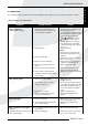
Depending on the construction of the concentric system,
the appliance must receive further settings; see Table 1 for
determining the conditions and section 6.8, Adjusting the
appliance, for the method.
6.5.2.2 Placing concentric system with wall
terminal
- Maintain a distance of at least 50 mm
between the outside of the concentric
system and the walls and/or the ceiling.
If the system is built in (for instance) a
cove, it should be made with non com-
bustible material all around it.
- Use heat-resistant insulation material
when passing through combustible
material;
- The rosette (mounting inner plate) of
the wall terminal is too small to seal
the Ø 250 mm opening when passing
through combustible material. That is why
you should fi rst apply a suffi ciently large
heat-resistant intermediate plate to the
wall. Then, the rosette is mounted on the
intermediate plate.
!Caution Some heat-resistant insulation materials
contain volatile components that will
spread an unpleasant smell for a prolon-
ged time; these are not suitable.
Place the concentric system as follows:
• Build the system up from (the connection stump of) the
appliance.
• Connect the concentric pipe pieces and the bend.
• On each connection, apply a clip binding with silicon sea-
ling ring.
• Use a self-tapping screw to fi x the clip binding to the pipe
on locations that cannot be reached after installation.
• Apply suffi cient clamps, so that the weight of the pipes
does not rest on the appliance.
• Determine the remaining length of the wall terminal;
• Make sure the wall terminal has the right dimensions.
Caution
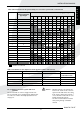
Table 1: Conditions for the adjustment of the appliance with a wall terminal
G20/25
Total Total number See Air inlet guide Baffl e Distance
number of of meters fi gure of
meters horizontal restriction
vertical pipe length in mm
pipe length (excluding
wall terminal)
1 - 4 >0 - 3 3a NO NO OPEN
1 - 4 0* 3b YES NO OPEN
* factory setting
Caution