PowerSeries PC1616/PC1832/PC1864 version 4.1 Installation Guide Note to Installer:Center pages contain important end user information. Leave with End User. WARNING: This manual contains information on limitations regarding product use and function and information on the limitations as to liability the manufacturer. The entire manual should be carefully read.
Table of Contents Section Description Page 1 1.1 1.2 1.3 1.4 1.5 1.6 1.7 1.8 1.9 1.10 Installation & Wiring............................................................................................ 1 Keybus Wiring .................................................................................................. 2 Zone Wiring...................................................................................................... 2 Zone Expanders.............................................................
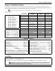
Section 1: Installation & Wiring Section 1: Installation & Wiring This Installation Guide provides the basic installation, wiring and programming information required to program the PowerSeries PC1616, PC1832 and PC1864 control panels. This guide shall be used in conjunction with the PowerSeries PC1616/1832/1864 Reference Manual which can be obtained from your local dealer or downloaded from the DSC web site at www.dsc.com.
PowerSeries - PC1616/PC1832/PC1864 1.1 Keybus Wiring The 4-wire KEYBUS (red, black, yellow and green) is the communication connection between the control panel and all modules. The 4 KEYBUS terminals of all modules must be connected to the 4 KEYBUS terminals of the main control panel.
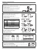
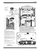
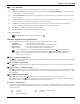
Installation PC1616/1832/1864 Wiring Diagram North America Only POWER LIMITED Stand Off PC Board Cable Tie (not supplied) recommended Cabinet 2. Position circuit board mounting holes over standoffs. Press firmly on board to snap-in-place. DSC UA503 Primary:120VAC/60Hz. Secondary: 16.5VDC 40VA DSCPTD 1640U Class II Transformer 220 1. Insert Stand off into cabinet mounting hole in the desired location. Snap-inplace.
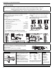
PowerSeries - PC1616/PC1832/PC1864 1.5 AUX Power Wiring The control panel can provide a maximum of 700mA of current for modules, powered detectors, relays, LED’s etc. If the total current required exceeds 700mA an additional power supply is required (e.g.,PC5200, PC5204). See list below. Min/max operating voltages for devices, sensors and modules is 9.5VDC - 14VDC Refer to the list of Compatible Devices on page 1 and/or the Reference Manual for the current draw of individual devices 1.
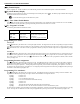
Section 2: User Commands Section 2: User Commands Any system keypad can be used to program or perform any keypad command. LED keypads use status and zone indicator lights to represent alarm functions and status. The LCD keypad displays the description and status indicator lights represent alarm functions and status. This section describes basic keypad commands. Refer to the PC1616/1832/1864 Reference Manual for detailed description of all keypad commands.
PowerSeries - PC1616/PC1832/PC1864 [4][2] Trouble Display Refer to Appendix D – Trouble Conditions, for troubleshooting assistance and a detailed description of all trouble conditions. [4][3] Alarm Memory Display The Memory light will be ON if an alarm occurred during the last armed period. Press [4][3]. The Memory light will flash and the keypad will display the zones that went into alarm. : To clear the Memory light, arm then disarm the system. [4][4] – Door Chime Enable/Disable Press [4][4].
Section 2: User Commands [4][6] – User Functions Press [4][6] followed by the Master Code, then press the number corresponding to the following functions. [1] Program Time and Date: Enter the time and date using the following format [HH:MM] [MM/DD/YY]. Program the time using military standard (e.g., 8:00 pm = 20:00 hours). [2] Auto-arm Enable/Disable: The keypad will emit 3 rapid beeps if the Auto-arm feature is now enabled and a steady 2-second tone if it is now disabled.
PowerSeries - PC1616/PC1832/PC1864 Section 3: Programming This section provides the information necessary to program all required features for a basic system as well as common applications. Refer to the PC1616/1832/1864 Reference Manual for a complete description of all programmable features. 3.1 How to Program: DSC recommends filling in the Programming Worksheet with the required programming information before programming the system.
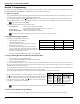
Section 3: Programming 3.5 Viewing Programming LED and LCD5501Z Keypads Any programming section can be viewed from an LED or LCD5501Z keypad. When a programming section is entered, the keypad will immediately display the first digit of information programmed in that section. The keypad displays the information using a binary format, according to the following chart: Press any of the Emergency keys (Fire, Auxiliary or Panic) to advance to the next digit.
PowerSeries - PC1616/PC1832/PC1864 Section 4 – Programming Descriptions The following is a brief description of the features and options available in the Power PC1616/1832/1864 control panel. Refer to the PC1616/ 1832/1864 Reference Manual for a complete description of all programming features, limitations and requirements.
Section 4 – Programming Descriptions [37] Night Zone: Functions like Interior Stay/Away but will remain bypassed if the user presses [ ][1] to re-activate Stay/Away zones when armed in the Stay mode [87] Delayed 24-Hour Fire (Wireless): Same as Delayed 24-Hour Fire (Hardwire) but must be used for wireless smoke detectors [88] Standard 24-Hour Fire (Wireless): Same as Standard 24-Hour Fire (Hardwire) but must be used for wireless smoke detectors Section [005] System Times After entering Section [005],
PowerSeries - PC1616/PC1832/PC1864 [20] Command Output 2: Activates when a [ ][7][2] command is entered on the selected partition – Command can be programmed to require a valid access code and output can be programmed to activate for the time programmed in Section [170] or programmed to latch.
Section 4 – Programming Descriptions Section [014] Second System Option Code Option Description [1] ON: the system squawks the bell output once when a partition is armed, twice when disarmed. OFF: the bell output does not activate. [2] ON: the system squawks the bell output every 10 seconds during the auto-arm pre-alert. OFF: the bell output does not activate. [3] ON: the system will squawk the bell output once every second during Exit Delay, 3 squawks per second for the last 10 seconds.
PowerSeries - PC1616/PC1832/PC1864 [5] ON: keypad backlighting enabled. OFF: keypad backlighting disabled. [6] ON: the system temporarily enables the Keypad Blanking feature if an AC failure is detected (to preserve the back up battery). OFF: the system will operate as normal. [7] ON: the keypad turns ON the Bypass light if zones are bypassed while the system is armed. OFF: the Bypass light turns OFF when the system is armed. [8] ON: the system supervises keypad tampers.
Section 4 – Programming Descriptions Section [020] Keypad Zone Assignment Enter the two-digit zone number to be assigned to each keypad assigned to a specific slot. Only one keypad can be assigned to a specific slot. See Keypad Assignment. Valid entries are from [00] to [64]. Section [021] Eighth System Option Code For Future Use Section [022] Ninth System Option Code Option [1-5] Description For Future Use [6] Refer to the PC1616/PC1832/PC1864 Reference Manual for RF Delinquency details.
PowerSeries - PC1616/PC1832/PC1864 [4] ON: the user can manually bypass the zone using the [ ][1] command. OFF: the zone cannot be manually bypassed. [5] ON: the partition can be armed even if the zone is violated (the zone will not affect the Ready status). OFF: the zone must be secure before arming. [6] ON: the system shuts down alarm reporting after the programmed number of alarms have occurred. OFF: the panel will always report the event if an alarm occurs.
Section 4 – Programming Descriptions Section [175] Auto-Arm Postpone Timer Program the time, in minutes, that the system will postpone automatic arming. After the programmed time, the system will attempt to auto arm again. If data [000] is programmed, the system will instead abort the auto arm sequence. Valid entries are [001] to [255].
PowerSeries - PC1616/PC1832/PC1864 Section [311] to [318] Partition Account Numbers Program the Partition Account Number for each active partition (Section [311] for partition 1, Section [312] for partition 2 etc.). When using the Automatic SIA format, these account numbers are not used. The system will use the System Account Number for all reporting events. For all formats other than SIA, program a HEX [A] for any digit [0] in the account number being used.
Section 4 – Programming Descriptions Section [380] First Communicator Option Code Option Description [1] ON: the system communicator is enabled. OFF: the communicator is disabled. [2] ON: the system transmits alarm restorals if the zone is restored and the bell has timed out. OFF: the system transmits alarm restorals immediately when the zone is restored. [3] ON: the panel uses rotary (pulse) dialing.
PowerSeries - PC1616/PC1832/PC1864 [6] [7-8] ON: the AC Failure Transmission Delay Timer will use hours. OFF: the delay will be in minutes. For Future Use Section [401] First Downloading Option Code Option [1] Description ON: the system answers incoming calls for downloading (either Programmed Number of Rings or Double Call). OFF: the system does not answer incoming calls for downloading. These settings do not affect the 6 hour DLS downloading window on power up.
Section 4 – Programming Descriptions PGM Output Option [01], [03] to [08], [11] to [22], [25] Option [3] Description ON: the PGM output will operate normally (switch to ground when activated). OFF: the PGM output will be normally ground and switch to open collector (open circuit) when activated. PGM Output Option [19] to [22] Option Description [4] ON: the PGM output will activate for the duration of the PGM Output Timer when the [ ][7][x] command is performed.
PowerSeries - PC1616/PC1832/PC1864 Section [701] First International Option Code Option Description [1] ON: configures the system for 50Hz AC. OFF: configures the system for 60Hz AC. [2] ON: the system uses the internal crystal for the internal panel clock. OFF: the system uses the AC frequency for the internal panel clock. [3] ON: the system will inhibit arming if a Low Battery or AC trouble condition is present. OFF: arming will not be inhibited.
Section 4 – Programming Descriptions Section [900] Special Installer Instructions Section [900]: Display Panel Version Only available with LCD5500 or PK5500 keypads. The system will display the version of the control panel (for example, [0410] indicates panel version 4.10). Section [901]: Installer Walk Test The system will turn Installer Walk Test ON. The Ready, Armed and Trouble LED’s will flash rapidly while the test is active.
PowerSeries - PC1616/PC1832/PC1864 Section [993] to [999]: Factory Default Module/Panel The following Sections can be used to factory default a module or the main control panel. Enter the appropriate Section, followed by the Installer Code, followed by the Section number (E.g.
Section 5: Programming Work Sheets Section 5: Programming Work Sheets 5.1 Index to Programming Work Sheets Programming Option Page [000] Keypad Enrollment .....................................................................26 [001]-[004] Zone Definitions................................................................26 [005] System Times.............................................................................27 [006] Installer’s Code...................................................................
PowerSeries - PC1616/PC1832/PC1864 5.2 Programming Worksheets Shaded programming sections indicate minimum programming trerquirements SIA FAR CP-01 defaults are indicated in gray text. Keypad Partition /Slot and Function Key Programming [000] Keypad Enrollment This must be done at each keypad requiring programming. [0] Slot address [Valid entries are 0-8 for the partition, 1-8 for the slot. (e.g.
5.2 Programming Worksheets Section Zone Def. Section Zone Def. Section Zone Def.
PowerSeries - PC1616/PC1832/PC1864 [006] Installer’s Code [007] Master Code [008] Maintenance Code Default 5555 I_______I_______I_______I_______I Default 1234 Default AAAA I_______I_______I_______I_______I I_______I_______I_______I_______I Programmable Output Options 01 02 03 04 05 06 07 08 09 10 11 12 13 14 Residential Burglary and Fire Bell Output For Future Use Sensor Reset [*][7][2] 2 Wire Smoke Support (PGM 2 only) System Armed Status Ready To Arm Keypad Buzzer Follow Mode Courtesy Pulse Syste
DSC PowerSeries Alarm System User Guide About Your Security System Keypad Display Symbols Your DSC Security System has been designed to provide you with the greatest possible flexibility and convenience. Read this manual carefully and have your installer instruct you on your system's operation and on which features have been implemented in your system. All users of this system should be equally instructed in its use.
Download complete User manual from www.dsc.com Emergency Keys [4] Commands Press the (F), (A) or (P) key for 2 seconds to generate a Fire, Auxiliary or Panic alarm. The keypad sounder will beep indicating that the alarm input has been accepted and transmission to the central station is underway. Ask your alarm company if the emergency keys are available on your system [4][1] Bypass/Re-activate Stay/Away Zones . Fire Keys can be disabled by the Installer.
DSC PowerSeries Alarm System User Guide 6-digit user code or press [4] to delete the user code. After the user code is programmed or deleted, enter another 2-digit user to be programmed or press [#] to exit. LCD Keypad: Press [4][5] followed by the Master Code. The keypad will display the first user (user 01) and include the letter ‘P’ in the bottom, right corner if the user code is programmed. Scroll to the appropriate user and press the [4] key to program the user (or enter the 2-digit user number).
Download complete User manual from www.dsc.com ’Split level arrangement: Smoke detectors are required where shown. Smoke detectors are optional where a door is not provided between living room and recreation room’. FCC COMPLIANCE STATEMENT CAUTION: Changes or modifications not expressly approved by Digital Security Controls could void your authority to use this equipment. This equipment has been tested and found to comply with the limits for a Class B digital device, pursuant to Part 15 of the FCC Rules.
5.
PowerSeries - PC1616/PC1832/PC1864 [017] Fifth System Options Opt Def 1 9 R WLS Key Does NOT use Access Codes 2 R R R R R 9 R R RF Jam Log after 5 Minutes 3 4 5 6 7 8 ON OFF 9 9 9 9 9 Audible RF Jam Trouble Beeps Double Hit Enabled Late to Close Enabled Daylight Savings Time Enabled Periodic Camera Test Enabled 9 Squawk on Away Key Arming/Disarming Only R R R R R R R R WLS Key Uses Access Codes RF Jam Log after 30 Seconds Silent RF Jam Trouble Beeps Double Hit Disabled Late to Close Disabled
5.
PowerSeries - PC1616/PC1832/PC1864 [101]-[164] Zone Attributes Zone Attribute Defaults (Y = Option ON; N = Option OFF): Bold entries are opposite for SIA CP-01 Attribute: ON OFF Zone Type: 00 Null Zone 01 Delay 1 02 Delay 2 03 Instant 04 Interior 05 Int. Stay/Away 06 Dly. Stay/Away 07 Dly. 24hr Fire (Hardw.) 08 Stand. 24hr Fire (Hardw.) 09 24hr Superv. 10 24hr Superv.
5.2 Programming Worksheets Section Zone # Zone Type** Audible/ Silent 1 Steady/ Pulsed 2 Chime No 3 Bypass No 4 Force* No 5 Swing No 6 Tx.
PowerSeries - PC1616/PC1832/PC1864 System Timers [165] Maximum Dialing Attempts to Each Telephone Number Default 005 I_______I_______I_______I Valid entries are 001-005 attempts For UL Listed Installations, 5-10 dialing attempts are required.
5.
PowerSeries - PC1616/PC1832/PC1864 Communications [301] First Telephone Number (32 Digits) I_____I_____I_____I_____I_____I_____I_____I_____I_____I_____I_____I_____I_____I_____I_____I_____I_____I_____I_____I_____I_____I_____I_____I_____I_____I_____I_____I_____I_____I_____I_____I_____I When using T-Link, program DCAA as the phone number.
5.
PowerSeries - PC1616/PC1832/PC1864 [334]-[337] Tamper Restoral Reporting Codes, Zones 01-64 Section [334] [335] [336] [337] Zone 01 Zone 02 Zone 03 Zone 04 Zone 05 Zone 06 Zone 07 Zone 08 I_______I_______I I_______I_______I I_______I_______I I_______I_______I I_______I_______I I_______I_______I I_______I_______I I_______I_______I Zone 09 Zone 10 Zone 11 Zone 12 Zone 13 Zone 14 Zone 15 Zone 16 I_______I_______I I_______I_______I I_______I_______I I_______I_______I I_______I___
5.
PowerSeries - PC1616/PC1832/PC1864 Call Direction Options [351]-[358] Alarm/Restore Communicator Call Directions Section Partition [351] [352] [353] [354] [355] [356] [357] [358] 1 2 3 4 5 6 7 8 Option 2 Option 1 2nd Telephone 1st Telephone Number (Def ON) Number (Def OFF) Option 3 Not Used (Def OFF) Option 4 Not Used (Def OFF) Option 5 Alt Comm (Def ON) Options 6,7,8 Future Use I________I I________I I________I I________I I________I I________I I________I I________I I________I I________I I_
5.
PowerSeries - PC1616/PC1832/PC1864 [382] Third Communicator Options Opt Def R R R R R R R R 1 2 3 4 5 6 7 8 ON OFF Contact ID Partial Closing Identifier is “5” 9 R Contact ID Partial Closing Identifier is “4” Alarm Communications Enabled During Walk Test* 9 R Alarm Communications Disabled During Walk Test Communication Cancelled Message Enabled (ON for SIA CP-01) 9 R Communication Cancelled Message Disabled Call Waiting Cancel Enabled** 9 R Call Waiting Cancel Disabled T-Link Interface Ena
5.2 Programming Worksheets [501]- [554]Programmable Output Attributes Program only the following attributes for the PGM options listed. All others will be ignored. PGM options are programmed in [009], [010] & [011]. PGM Attribute Defaults (Y = Attribute ON; N = Attribute OFF): Attribute: 1 2 3 4 5 ON Not used Not used True Output Follows Timer OFF — — Inverted On / Off 6 Code Req. 7 8 Not used Not used Not used No Code Req.
PowerSeries - PC1616/PC1832/PC1864 Section PGM # Main Board Output Type* 1 2 3 [501] 1 ( [502] 2 ( 4 ) I________I I________| I________| I________| ) I________I I________| I________| I________| 5 6 7 8 I________| I________| I________| I________I I________| I________| I________| I________I Main Board / PC5208 [503] ** 3 ( ) I________I I________| I________| I________| I________| I________| I________| I________I [504] ** 4 ( ) I________I I________| I________|
5.
PowerSeries - PC1616/PC1832/PC1864 Special Installer Functions [900] Panel Version Displayed [901] InstallerWalk Test Mode Enable/Disable [902] Module Supervision Reset [903] Module Supervision Field [904] Wireless Module Placement Test [905] - [909] For Future Use [990] Installer Lockout Enable [991] Installer Lockout Disable [992] For Future Use [993] Restore Alternate Communicator to Default Programming [994] For Future Use [995] Restore Escort5580 to Default Programming [996] Restore PC5132 to Default P
Appendix A: Reporting Codes Appendix A: Reporting Codes The following tables contain Contact ID and Automatic SIA format reporting codes. For more information on reporting code formats and notes about individual reporting codes, (see Section 5.6 Communicator Programming PWS Sect 6). Contact ID The first digit (in parentheses) will automatically be sent by the control. The second two digits are programmed to indicate specific information about the signal.
PowerSeries - PC1616/PC1832/PC1864 Dialer Direction* Automatic Contact ID Codes SIA Auto Rep Codes** Section # Reporting Code Code Sent When... [345]-[346] Auxiliary Power Trouble/ Rest. Aux voltage supply trouble/restoral MA/R (3) 12 YP-00/YQ-00 [345] TLM Failure Telephone line monitoring trouble MA/R (3) 51 LT-01 [346] TLM Restore Telephone line restored MA/R (3) 51 LR-01 [345]-[346] Gen System Trouble/Rest.
Appendix B: UL Listed Commercial and Residential Installations Appendix B: UL Listed Commercial and Residential Installations The installation requirements listed below must be met for the following grades of service. Central Station and Police Connect (Standard or Encrypted Line Security Service) The installation must use T-Link module which communicates over LAN/WAN to the Sur-Gard MLR-IP receiver or the TL200/250 which communicates over LAN/ WAN/Internet to the SG System III receiver.
PowerSeries - PC1616/PC1832/PC1864 Appendix C: SIA False Alarm Reduction SIA Feature Programming Section Comments Range/Default Requirement Exit Time [005], 3rd entry Access to Entry and Exit delays for each partition and Bell Time Out for the system For Full or auto arming: Range:45- 255 seconds Default: 60 sec.
Appendix D: Troubleshooting Guide Appendix D: Troubleshooting Guide Testing: • • Power up system Program options as required (See Programming Section) NOTE: For advanced programming refer to the PC1616/1832/1864 Reference Manual • • Violate, then restore zones Verify correct Reporting Codes are sent to the Central Station Troubleshooting: LCD Programmable-Message Keypad • • • Press [✱][2] to view a trouble condition.
PowerSeries - PC1616/PC1832/PC1864 Trouble Cause Trouble [1] Service Required [1] Low Battery Troubleshooting Press [1] to determine specific trouble Main panel battery less than 11.1VDC NOTE: This trouble condition will not clear until the battery voltage is 12.5VDC min., under load. [2] Bell Circuit Bell+, Bell-...Open Circuit NOTE: If battery is new allow 1 Hr. for battery to charge. • Verify voltage measured across AC terminals is 16-18 VAC. Replace transformer if required.
Appendix D: Troubleshooting Guide Trouble Cause Troubleshooting No AC at panel AC input terminals Verify voltage measured across AC terminals is 16-18VAC. Replace transformer if required. Trouble [2] AC Failure Trouble [3] Telephone Line Trouble Phone Line Voltage at TIP, RING on main panel less than 3VDC • • Measure the voltage across TIP and RING on the panel: • No phone off-hook – 50VDC (approx) • Any phone off-hook – 5VDC (approx) Wire incoming line directly to TIP and RING.
PowerSeries - PC1616/PC1832/PC1864 Trouble Cause Troubleshooting Trouble [5] Zone Fault (Cont.) One or more wireless devices have not checked in within the programmed time • • A short circuit is present on one or more zones with double end-of-line resistors enabled • • Trouble [6] Zone Tamper Remove the wire leads from Z and COM terminals and measure the resistance of the wire leads. • A short circuit indicates a short in the wiring. Connect a 5.
NOTES
NOTES
Note to Installers Limited Warranty This warning contains vital information. As the only individual in contact with system users, it is your responsibility to bring each item in this warning to the attention of the users of this system. Digital Security Controls warrants the original purchaser that for a period of twelve months from the date of purchase, the product shall be free of defects in materials and workmanship under normal use.
FCC COMPLIANCE STATEMENT CAUTION: Changes or modifications not expressly approved by Digital Security Controls could void your authority to use this equipment. This equipment has been tested and found to comply with the limits for a Class B digital device, pursuant to Part 15 of the FCC Rules. These limits are designed to provide reasonable protection against harmful interference in a residential installation.