PC4010 v3.0 • Installation Manual DLS-2 v1.3 WARNING: This manual contains information on limitations regarding product use and function and information on the limitations as to liability of the manufacturer. The entire manual should be carefully read.
WARNING Please Read Carefully N o te t o I n s t al le r s This warning contains vital information. As the only individual in contact with system users, it is your responsibility to bring each item in this warning to the attention of the users of this system. S ys te m Fa i lu r e s This system has been carefully designed to be as effective as possible. There are circumstances, however, involving fire, burglary, or other types of emergencies where it may not provide protection.
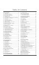
Ta b le o f Co nte nts Section 1: Introduction 1 1.1 Out Of The Box .....................................................................1 1.2 Specifications and Features ................................................1 Section 2: Installation and Wiring 2 2.1 Planning the System ............................................................2 2.2 Terminal Descriptions .........................................................2 2.3 Current Ratings – Alarm Control Panel and Modules ...3 2.
PC 4 0 1 0 Wiri ng Di ag ram NOTE: Do not remove the foam from the back of the circuit board.
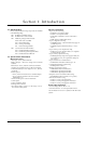
S ec tion 1: Intro d u cti o n 1.1 Out Of The Box Please verify that the following components are included in the PC4010 package. ❑ 1 PC4050C or PC4001C cabinet ❑ 1 PC4010A main control module ❑ 1 Hardware package which includes: ❑ 16 EOL resistors (5600Ω) ❑ 1 Black cabinet plug ❑ 1 Green ground strap ❑ PCB mounting standoffs ❑ 1 set of documents which includes: ❑ 1 PC4010 Installation Manual ❑ 1 PC4010 Programming Worksheets ❑ 1 PC4010 Instruction Manual 1.
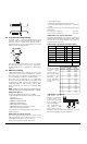
S e ction 2 : I n s tal l ati o n and Wi ri ng 2.1 Planning the System 2 2.2 Terminal Descriptions NOTE: This system should be installed and serviced by qualified security professionals. The following terminals appear on the PC4010 Alarm Control Panel: The speed and efficiency of installing a MAXSYS system will be greatly enhanced by planning the installation.
S e c t i o n In order for the system to operate properly, the power output of the alarm control panel and power supply modules cannot be exceeded. Use the data below to ensure that the available current is not exceeded. PC4010 Alarm Control Panel AUX - 500mA available for devices connected to the AUX, SAUX+ and PGM terminals and modules connected to Combus terminals. At least 100mA must be reserved for the Combus.
the wire to calculate the maximum distance (see “Capacitance Limits” below). 4. The total capacitance of the Combus wiring must not exceed 80nF (see “Capacitance Limits” below). Line Loss When current is drawn through a piece of wire, voltage will be lost due to the wire’s resistance. This voltage loss must be considered for all installations. To ensure proper operation, at least 12.5VDC must be applied to all modules on the system (when AC is applied and the battery is fully charged). If less than 12.
S e c t i o n 2 : I n s t a l l a t i o n a n d W i r i n g Double End of Line (DEOL) All Double EOL zones have two 5600Ω resistors across them. DEOL loops will allow the panel to detect zone faults, zone tampers, violated zones and restored zones. Resistors should always be placed at the device end of the wire run. The power for the 4-wire detectors must be supervised with an end-of-line relay (RM-1). The contacts of that relay are wired in series with the zone end-of-line resistor.
• input debounce time • addressable reporting and confirmation time • processing time required by the panel to activate the output These response times are worst case and typical response will be faster. 1 to 32 devices on the loop ................................ up to 2.5s 33 to 56 devices on the loop .............................. up to 5.4s 2.7 Programmable Output Wiring The PGM output is a programmable terminal and will connect to +12V when activated. The terminal can sink a maximum current of 50mA.
S e c t i o n Once the devices are connected, the PGM terminal must be configured for AML operation and each device must be enrolled. See Section 4.4 “Enrolling AML Devices” for instructions 2.9 Wiring Powered Devices (AUX, SAUX+) I n s t a l l a t i o n These terminals are used for powering bells, sirens or other devices requiring steady output voltage on alarm. The panel can provide up to 2A short-term or 700mA long-term current. The output is supervised.
The EGND terminal must be connected to earth ground to enable ground fault detection. A Ground Fault trouble will be indicated if any conductor on the system has a resistance to earth ground of 40kΩ or less. Only earth ground the main panel and the first module connected to the telephone line. hours (Ah). To determine the appropriate battery size, perform the following: 1. Calculate the total current required when the panel is not in alarm. This is the standby current. See Section 2.
S e c tion 3: Ho w to P ro g ram 3.1 Introduction to Programming The PC4010 is programmed via a menu system. Use the arrow keys (<>) to scroll through different menu options and press the [*] key to select the menu option displayed. Continue this procedure until the required program section is displayed, then press the [*] key to select it. To arrive at a program section where data can be entered may require scrolling and selecting items from several menus. Press the [#] to return to the previous menu.
3.4 Programming Hexadecimal Data Hexadecimal or “Hex” digits are often required for a programming item, such as telephone numbers and reporting codes. To insert a Hex digit into a given entry, press the [*] key to enter the Hex menu. Use the arrow keys to scroll through the each Hex digits (A through F). When the desired letter is displayed, press the [*] key.
S ec tion 4 : M o d u l e E nro l l me nt 4.1 Enrolling Keypads and Modules Once the wiring of all keypads and modules is complete, they must be enrolled on the system. Apply power to the system by first connecting the battery, followed by the AC transformer. All LCD keypads will display the software version number of the keypad. NOTE: Make sure all power to the system is OFF when connecting modules. NOTE: Record the location and number of each module for future reference.
4.3 Confirming Modules Ref # [0202] then scroll to desired module In case module numbers were not recorded, you can verify this information through the “Confirm Module” menu in the “Module Hardware” programming section in installer’s programming. This works just like enrolling modules. You will be prompted to “Press Any Key On Desired Unit” in the case of keypads and “Create Tamper on Desired Unit” in the case of modules. Once the correct action is taken, the keypad will display the module number (e.g.
S e c tion 5 : Parti ti o ns and Z o ne s 5.1 Zone Supervision Ref # [000204] “Zone Supervision” The control panel must be instructed to supervise either No End of Line, Single EOL or Double EOL zone loops. These three options are described in Section 2.5 “Zone Wiring.” To program this option, perform the following: 1. Enter installer’s programming by pressing [*] [8] [Installer’s Code]. 2. Enter reference number [000204] and press [*]. 3. Scroll through the three supervision types.
Scroll to the partition to be deleted, then press [*]. When a partition is deleted, the programming assigned to it will not be erased. If the partition is re-enabled, the programming that was entered will still be there. NOTE: When a partition is deleted, the zones assigned to it are removed from the Zone Assignment. Copying Partitions Ref #: [0102] Enter this section to copy the programming from one partition to another one.
S e c t i o n Zone Types The following is a description of each zone type: Standard Delay (00) Standard Delay zones have an entry and exit delay. The exit delay will begin as soon as arming is initiated. The delay zone may be opened and closed during the delay time without causing an alarm. After the exit delay time has expired, the zone is armed. Opening the zone will start the entry delay. If the panel is disarmed before the entry time expires, no alarm will be generated.
NOTE: Waterflow zones always require single EOL resistors regardless of any other programming. Refer to the wiring diagram or Section 2.9 “Zone Wiring” for zone configuration. NOTE: This zone type must not be used as a global zone. If a keyswitch zone has been tampered or faulted, the zone must be restored before it can be used to arm or disarm the system.
S e c t i o n P a r t i t i o n s a n d Z o n e s • Waterflow Del – This will enable the waterflow delay for waterflow zones. Waterflow delay operates similar to transmission delay except both the fire output and communications will be delayed. If the zone is restored before the programmable delay time, no transmission is sent. Select [Y] to enable this feature. If [N] is selected, the panel will immediately activate the fire output and communicate to central station.
S ec tion 6 : Ke yp ad O p e rati o n 6.1 Partition Keypads A partition keypad is a keypad that is assigned to a partition. The partition keypad will primarily control the partition to which it is assigned. However, a user will also be able to control other partitions from the partition keypad, if their access code allows it. When a user enters their code to disarm the partition at a partition keypad, the partition to which the keypad is assigned will disarm.
S e c t i o n Ref #: [000200] When the Keypad Blanking toggle option is enabled, all partition keypad lights – including the display – will turn off. The keypad lights and display will remain off until a key is pressed. If the Keypad Blanking Requires Code option is enabled, the user will be required to enter their access code in order for the keypad lights and display to turn on. To program these options, enter reference number [000200] and scroll to the following items.
When the option is disabled, the alarm memory will only be displayed when the system is disarmed. 6.9 Zone Bypass Display Ref #: [000200] Enable the Bypass Display system toggle option, to allow users to view bypassed zones while the system is armed. Users can view bypassed zones by pressing the [<][>] keys. When the option is disabled, users will only be able to view bypassed zones using [*][1] when the system is disarmed. NOTE: Bypass Display must be disabled on UL listed systems. 6.
S e c t i o n 6 : K e y p a d O p e r a t i o n S EC T ION 1 2 3 4 5 6 7 8 9 1 0 1 1 1 2 13 14 1 5 1 6 Command Output X (X=1-8) (13-20) This function key provides the user with a simple method for activating a PGM Output programmed as Command Output option #1-8 (see Section 11.4 “PGM Output Options”). Once this key is pressed, the user may need to enter a valid access code if the Cmd.Out X Rq Cd option is enabled for the command output.
S e ct i on 7 : I n s ta l l e r and A cce s s Co d es NOTE: Security codes should be changed from their default settings to ensure the security of the system. Do not program codes that can be easily guessed. 7.1 Installer’s Code Ref #: [000000] The installer’s code must be entered to access the installer’s programming mode. The default installer’s code is [4010] for the 4-digit option and [401000] for the 6-digit option. Enter a new code using numbers from 0 to 9 only.
S e c t i o n Partition Options Ref # [0100XX01] where XX = Partition 01-04 The following access code options are programmed by partition. Only access codes assigned to the selected partition will operate according to the following programmed items. • Bypas Req Code - If enabled, the user will be required to enter an access code in order to bypass a zone on this partition.
S e cti on 8 : A r m i ng and Di s armi ng 8.1 Arming and Disarming Options Ref #: [0100XX01] where XX = Partition 01-04 The following arming and disarming options are programmed by partition. If the Bell Squawk option is enabled, outputs will activate once briefly when the partition is armed and twice when the partition is disarmed. All outputs programmed for “Fire and Burg,” “Inv Fire/Burg,” “Burg Only” or “Inv Burg Only” will squawk.
S ec tion 9 : Entry and E xi t De l ay Upon arming, the panel will begin the Exit Delay. If the “Exit Delay Aud” option is enabled, the keypad will beep every second until the exit delay expires (see Section 9.2 “Entry and Exit Delay Options”). The keypad will beep rapidly for the last 10 seconds of the exit delay to warn the user that the system is about to arm. Upon entry, if a Delay type zone is violated, the panel will begin an Entry Delay. The keypad will emit a steady tone.
S e c tion 1 0 : S y s te m P ro grammi ng 10.1 AC/DC Power Options Ref # [000200] The following options are used to determine the power settings for the system. Press [*] to toggle each option on or off. • Power Up Shunt: If enabled, all zones will be inactive during the first two minutes of power up to prevent causing false alarms. (Default = Yes) NOTE: If AML zones are being used, ensure that the Power Up Shunt option is enabled.
S e c t i o n The following event messages can be modified from their default settings to suit the user’s needs. To enter new labels, enter each character as outlined in “Programming System Labels” on page 14. These messages will only appear if the [*][6] “Special Messages” toggle option is enabled by the end user/system administrator. The zone tamper and zone fault messages will be displayed regardless of the [*][6] Special Messages option setting.
Periodic Tx Days Ref #: [0004020400] Enter the number of days between test transmissions. Valid entries are from 001 to 255. The default setting is 001. If the Test Tx in Min communicator toggle option is enabled, the “Periodic Tx Days” counter will be the number of minutes between test transmissions (Ref #: [000401] and scroll to option). If disabled, the “Periodic Tx Days” counter will be the number of days between test transmissions.
S e c ti on 11 : P ro g rammab l e O u tp ut s 11.1 Main Panel Outputs The main panel has three programmable outputs: Bell, SAUX+, and PGM1. Adding PC4216/PC4204/PC4702 modules can expand the number of outputs. All outputs can be individually programmed to activate for any of the programmable output options (listed in Section 11.2 “Programmable Output Options”). SAUX+ Output Ref #: [0005] The SAUX+ output can supply up to 300 mA at 12VDC. It can be programmed as one of the output options (see Section 11.
TLM and Alarm (14) The output will activate when a telephone line trouble is present and an alarm occurs on any of the selected partitions. Failure To Communicate (15) The output will activate when a Failure to Communicate trouble is present. The output will stay activated until a successful communication is sent to the central station. Communications Active (16) The output will activate while the panel is attempting to communicate with the central station.
S e c t i o n Command Output Labels Ref #: [0100XX06YY] where XX = partition number (0104), YY = command output number (01-08) Program command output labels in this section. All system display labels are programmed in a similar fashion. For instructions on programming labels, see Section 5.4 “Zone Programming.” Police Output (46) The output will activate when a Cross Zone/Police Code Alarm reporting code is transmitted for any of the selected partitions.
Section 12: Communications Programming All options concerning communications can be programmed in the following sections, including telephone numbers, reporting codes, account numbers, communicator toggle options and miscellaneous communicator options. By default, the Comm Enabled toggle option is on to enable communications. To disable communications, enter reference number [000401]. “Comm Enabled” will appear on the display. Press [*] to toggle the option to [N]o.
S e c t i o n • Restore on Disarm: If enabled, the panel will send the restoral reporting code when the partition has been disarmed. The panel will not send another alarm transmission for the zone until the partition is disarmed. If disabled, the panel will send the restoral immediately when the zone is restored. (Default = No) NOTE: DO NOT enable this feature if the previous “Restore on Bell Time Out” option is enabled. If Bell Shutdown is to be used, DO NOT enable this option.
Tone Delay before attempting to redial. If disabled, the panel will not search for busy tone when dialing the telephone number. (Default = No) • 1300 Hz ID: If enabled, the panel emits a 1300Hz identification tone from the time it dials to the time it hears the handshake from the receiver. If disabled, no identification tone is emitted. (Default = No) NOTE: This option should not be used with Pager 2, Pager 3 or Contact ID formats. This feature should not be used in North America.
S e c t i o n SIA 1 Account# Ref #: [000401] and scroll to option If the “SIA 1 Account#” toggle option is enabled, the SIA communication format will send the system ID code along with the partition number with each data transmission. If disabled, the communication format will use all eight Partition ID codes to identify partition events. If this option is enabled, partition account numbers are not required.
S ec tion 1 3 : Do wnl o ad i ng NOTE: DLS-2 v1.3 is required 13.1 Downloading Options Downloading Telephone Number Ref #: [000302] Enter the telephone number for the downloading computer (only applies if the User Call Up, Periodic DLS, or DLS Callback option is enabled). For instructions on programming telephone numbers, see Section 12.1 “Telephone Numbers.” Panel ID Code Ref #: [000303] The 4-digit panel identifier code will identify the panel to the downloading computer.
S ec tion 1 4 : E ve nt Sche d u l i ng Event scheduling allows for a variety of timed events to occur on specific dates and at specific times. Openings and closings can be suppressed during high traffic times, outputs may be programmed to follow date schedules and partitions may be auto-armed and auto-disarmed at specific times 14.1 Date Schedules Ref #: [001001] The panel uses date schedules to control the period during which an event will occur.
14.3 Open/Close Suppression Ref #: [001000] Open/Close Suppression will prevent the communication of openings or closings for the partitions following a programmed date schedule. When an Open/Close Suppression schedule is active, openings or closings for the selected partitions will be logged to the event buffer but no transmission will be made to the central station. There are 99 Open/Close Suppression Schedules. Each is capable of suppressing openings or closings for the selected Partitions, but not both.
S e ction 1 5 : L I NK S Co mmu ni cati o n s 15.1 LINKS1000 (Cellular Communications) When using a LINKS1000 Cellular Communicator as a primary or backup means of communicating to the central station, the following sections must be programmed. For instructions on programming telephone numbers, please refer to Section 12.1 “Telephone Numbers.
Section 16: Diagnostics and Troubleshooting 16.1 General Diagnostics Ref #: [04] The diagnostics function is designed to help you track down any problems with the installed modules. If there is no problem the keypad will display “PC40X0 System No Faults Found.” If there is a problem, the keypad will display “Error... Module.” This message will be accompanied by either “E” “T” or “LV” followed by a number. The number represents the module (see list below).
S e c t i o n D i a g n o s t i c s a n d T r o u b l e s h o o t i n g 16.5 System Fault Squawk If the Sys.Flt.Squawk option is turned on, when the system detects a zone tamper, zone fault or a module tamper, all the burglary bell outputs will squawk once every 5 seconds. The “squawks” will be silenced when the alarm is silenced or a key is pressed on that partition. By default this option is off.
A p p e n d ix A: R e p o rti ng Co d e s Notes on Contact ID The following is a list of Contact ID reporting codes. The first digit (in parentheses) will automatically be sent by the control. The last two digits are programmed to indicate specific information about the signal. For example, if zone 1 is an entry/exit point, the alarm reporting code could be programmed as [34]. The central station would receive the following: *BURG - ENTRY/EXIT - 1 In the above example, the “1” indicates the zone in alarm.
Dialer Direction* Contact ID SIA Auto Rep Codes** user code # 129-1000 used to arm partition O/C (4) A2 CL-UUU Partial Closing one or more zones intentionally bypassed when partition armed O/C (4) 56 CW-000 Automatic (Scheduled) Closing auto arming according to schedule O/C (4) A3 CA-000 Ref. # Reporting Code Code Sent When...
A p p e n d ix B : Z o ne R e p o rti ng Co d es For notes on Contact ID and SIA reporting codes, see Appendix A. Zone Definition Contact ID* Zone Alm/Rest. SIA Auto Rep Codes** Zone Zone Troub/Tam Fault/Rest. Alm/Rest. Zone Alm/Rest. Zone Troub/Tam Alm/Rest. Zone Fault/Rest.
A pp e n d ix C : ASCII Characte rs 45
Ind e x A D Access Code grand master 22 guard 22 options 22 second master 22 walk test 22 Access Levels 23 Account Number 13, 32 Addressable Loop current 6 enrolling devices 12 moving devices 12 panel key 12 removing devices 12 response time 6 wiring 6 AML.
UL Listed Commercial and Residential Installations The installation requirements listed below must be met for the following grades of service. Grade A Local The installation must have a bell UL Listed for mecantile local alarms (AMSECO MBL10B) with Model AB-12 bell housing. The digital communicator must be enabled. The control panel must be in the PC4004C Attack Resistant Enclosure.
©1999 Digital Security Controls Ltd. 1645 Flint Road, Downsview, Ontario, Canada M3J 2J6 (416) 665-8460 • Fax (416) 665-7498 • 1-800-387-3630 www.dscgrp.com Printed in Canada 29003124 R001 Limited Warranty Digital Security Controls Ltd. warrants the original purchaser that for a period of twelve months from the date of purchase, the product shall be free of defects in materials and workmanship under normal use. During the warranty period, Digital Security Controls Ltd.