
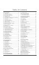
Installation manual


4
the wire to calculate the maximum distance (see
“Capacitance Limits” below).
4. The total capacitance of the Combus wiring must not
exceed 80nF (see “Capacitance Limits” below).
Line Loss
When current is drawn through a piece of wire, voltage
will be lost due to the wire’s resistance. This voltage loss
must be considered for all installations.
To ensure proper operation, at least 12.5VDC must be
applied to all modules on the system (when AC is
applied and the battery is fully charged). If less than
12.5V
DC is applied, system operation will be adversely
affected.
To correct the problem, try any or all of the following:
1. Connect a PC4204 power supply near the module to
provide power to the Combus.
2. Reduce the length of the Combus run to the module.
3. Increase the gauge of wire.
Capacitance Limits
An increase in capacitance on the Combus will affect
data transmission and will cause the system to slow
down. Capacitance will increase for every foot of wire
added to the Combus. The capacitance rating of the wire
used will determine the maximum length of the Com-
bus.
For example, 22-gauge, non-shielded, 4-conductor wire
has a typical capacitance rating of 20 picofarads per foot
(which is 20nF/1000’). For every 1000' of wire added –
regardless of where it is run – the capacitance of the
Combus will increase by 20nF.
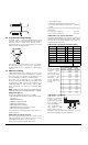
The following chart indicates the total Combus wire
allowed depending on the capacitance rating of the wire
used:
Wires run in parallel also increase Combus capacitance.
For example, when using 20nF wire, the following
would be some of the combinations allowed:
• Four wire runs at 1000'/305m each
• Six wire runs at 666'/203m each
• Eight wire runs at 500'/152m each
• 10 wire runs at 400'/122m each etc…
NOTE: Contact the wire manufacturer for the capaci-
tance ratings of the wire being used.
PC4204 Power Supply
PC4204 power supply modules are required to power
additional modules and devices when the total current
from the main panel is insufficient. A PC4204 should also
be used if excessive line loss is encountered.
PC4204 Current Requirement
AUX - 1.5A available for devices connected to the AUX
terminal, including devices connected to relay outputs
and modules connected for Combus repower (see Sec-
tion 2.4 “Combus Operation and Wiring”).
Combus Repower
Only Relay 1 on the PC4204 can be used for Combus
repower. The Combus must be wired to the PC4204
according to the following diagram for Combus
repower:
PC4204
IMPORTANT NOTE: Do not use any power supply
other than the PC4204 to repower the Combus. In the
event of a power surge or transient, a module may
lock up and cease to communicate with the control
panel. If the panel loses communication with the
module, it will initiate a module reset and will power
down the Combus for five seconds in an attempt to
reset the problem module. After five seconds, the
panel will reapply power to the Combus and the
problem module should begin to operate as
intended.
If a power supply other than the PC4204 is used, the
Combus repower function will not operate as
intended.
NOTE: New versions of the PC4204 power supply
module have a jumper marked ‘J1’. Ensure that this
jumper is configured for “Combus Relay.” Otherwise,
the power reset function will not operate. For more
information regarding the PC4204, please refer to the
PC4204 Installation Instructions.
2.5 Zone Wiring
Zones on the system are wired according to the diagrams
below. Once you have selected which type of zone super-
vision you require, you must program the “Zone Super-
vision” section. See Section 5.1 “Zone Supervision” for
instructions.
NOTE: Fire, LINKS Supervisory, LINKS Answer or
Forced Answer zones always use single EOL supervi-
sion, regardless of the programmed zone supervision.
No End of Line (No EOL)
All No EOL zones are normally closed
loops. The zone will be violated when it
is open.
Wire Capacitance per
1000'(300m)
TOTAL Combus Wire
Length
15nF 5300'/1616m
20nF 4000'/1220m
25nF 3200'/976m
30nF 2666'/810m
35nF 2280'/693m
40nF 2000'/608m