
Installation manual


Section 2: Installation and Wiring
5
SECTION 1 2 3 4 5 6 7 8 9 10 11 12 13 14 15 16
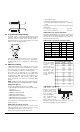
Single End of Line (EOL)
All Single EOL zones have a 5600Ω resistor across them.
If the zone is shorted or open, it will be violated. Resis-
tors should always be placed at the device end of the
wire run.
If programmed as a fire or waterflow zone, the open
zone will generate a trouble condition and the short will
generate an alarm.
Double End of Line (DEOL)
All Double EOL zones have two 5600Ω resistors across
them. DEOL loops will allow the panel to detect zone
faults, zone tampers, violated zones and restored zones.
Resistors should always be placed at the device end of
the wire run.
NOTE: Only normally closed detection devices can be
used with this type of zone supervision. Only one nor-
mally closed contact can be connected to each zone;
multiple detection devices or contacts on one loop are
not allowed, as the tamper condition will not be mon-
itored.
2.6 Specialized Zone Wiring
Some zones require wiring configurations unique to the
selected zone type. These zones are listed below. For
information regarding the various zone types, please see
Section 5.4 “Zone Programming.”
Fire Zone
This zone type uses normally open contacts. The zone
will initiate a fire alarm when the loop is shorted (con-
tacts close). A Fire Zone trouble will be generated when
the loop is opened (wire break). Typically, fire alarm initi-
ating contacts originate from 4-wire smoke detectors.
These types of detectors must be wired as shown in the
diagram below.
The power for the 4-wire detectors must be supervised
with an end-of-line relay (RM-1). The contacts of that
relay are wired in series with the zone end-of-line resis-
tor. With the relay energized, the relay contacts are
closed and the zone is normal. If the power is lost, the
relay de-energizes, the contacts open and a zone trouble
is initiated.
Multiple fire initiating normally open contacts may be
used in parallel on the loop. Do not include burglary or
other types of devices on a fire zone.
NOTE: Minimum 18 AWG wire is required for Listed
Residential Fire Alarm Systems.
Keyswitch Zone
Zones programmed as keyswitch arming zones must be
wired according to one the following diagrams:
LINKS Supervisory Zone
This zone is for use with a LINKS1000/LINKS2150/
LINKS2450 only. If the LINKS experiences a trouble con-
dition, a LINKS output can be used to violate this zone
type and the event will be reported to the central station.
See the corresponding LINKS Installation Manual for
wiring information.
LINKS Answer Zone
This zone is for use with a LINKS1000 only. In case of a
telephone line failure, the panel can be uploaded/down-
loaded via the cellular network. If the LINKS detects an
incoming call, it will activate an output that can be used
to violate this zone type. This will force the panel to
answer the cellular call and will begin communications
with the downloading computer.
This zone must be programmed as LINKS Answer and is
wired according to the following diagram: