
Installation manual


36
• SIA - This format uses 300 Baud FSK as the communi-
cation medium. The account code can be 4 or 6 hexa-
decimal digits in length, all reporting codes must be 2-
digits in length. The SIA format will transmit a 4- (or 6-
digit account code, a 2-digit identifier code and a 2
digit reporting code. The 2-digit identifier is pre-pro-
grammed by the panel.
Telephone Line Monitoring (TLM)
When the TLM Enable
TLM EnableTLM Enable
TLM Enable option is selected, the panel will
supervise the telephone line and will indicate a Trouble
condition if the telephone line is disconnected.
If the TLM Enable
TLM EnableTLM Enable
TLM Enable option is ON, the panel will check the
telephone line every 10 seconds. If the telephone line volt-
age is below 3V for the number of checks programmed in
the TLM Trouble Delay
TLM Trouble DelayTLM Trouble Delay
TLM Trouble Delay section, the panel will report a
TLM Trouble. The default number of checks is 3. Enter a
number from (000) to (255) in the TLM Trouble Delay sec-
tion to change the number of checks before the TLM Trou-
ble is reported. Programming a delay means that a
momentary interruption of the telephone line will not
cause a Trouble condition.
If the TLM Trouble Beeps When Armed
TLM Trouble Beeps When Armed TLM Trouble Beeps When Armed
TLM Trouble Beeps When Armed option is enabled,
the panel will indicate a TLM Trouble at the keypad while
the system is armed. To activate the bell output in the case
of a TLM Trouble while the system is armed, the TLM
TLMTLM
TLM
Audible (Bell) When Armed
Audible (Bell) When Armed Audible (Bell) When Armed
Audible (Bell) When Armed option must be selected.
When the Trouble condition is restored, the panel can
send a TLM Restoral
TLM Restoral TLM Restoral
TLM Restoral reporting code. Any events which
occur while the telephone line is down will also be com-
municated.
If the LINKS1000 Cellular Communicator, or LINKS2X50
is being used, the panel can be programmed to report a
TLM Trouble
TLM Trouble TLM Trouble
TLM Trouble reporting code.
[351]-[376] - Communicator Call Directions
For events from each Call Direction group the control
panel can call 2 different phone numbers and use the
LINKS as backup or as a redundant communicator for
one or both numbers. The third phone number can only
be used as a backup or alternate to the first.
Each report falls under one of the following 5 Groups:
1. Partition X Alarms & Restorals
2. Partition X Openings & Closings
3. Partition X Tampers & Restores
4. System Maintenance Alarms & Restorals
5. System Test Transmissions
Each group can be assigned to the following Call Direc-
Each group can be assigned to the following Call Direc-Each group can be assigned to the following Call Direc-
Each group can be assigned to the following Call Direc-
tions
tionstions
tions
1. Option 1 - 1st Telephone Number (and 3rd Telephone
Number if enabled for alternate or backup)
2. Option 2 - 2nd Telephone Number
3. Option 3 - 1st Telephone Number via LINKS (and 3rd
Telephone Number if enabled for alternate or backup)
4. Option 4 - 2nd Telephone Number via LINKS
5. Option 5 - Alternate Communicator. This allows the
panel to have control of what types of events the
LINKS2X50 products will communicate. This Call Direc-
tion is enabled at default.
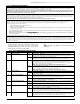
[377] - COMMUNICATION VARIABLES
Swinger Shutdown (Alarms & Restores)
This value defines the number of attempts (alarm and restoral pairs) per zone that the communicator will make before it shuts down for that zone (’swinger
shutdown’). Program 001 or 002 in this entry. When programmed as 000, the communicator will shut down after 2 Alarm/Restoral pairs.
Different limits can be programmed for
Zone Alarms
,
Zone Tampers
and
Maintenance
signals. After the panel has communicated the programmed number
of transmissions for an event it will no longer report that event until the swinger shutdown is reset. For example, the swinger shutdown limit for Zone Alarms is
set to [001]. The panel will not send more than 1 alarm signal for each zone with a swinger attribute until the swinger shutdown is reset.
The Bell output will not be activated for alarms on zones that have exceeded the limit of alarms set in the Swinger Shutdown counter. Swinger shutdown on
global zones will log once to the System Area.
NOTE: Swinger Shutdown will reset on all partitions when any partition on the system is armed, or every day at midnight. Once reset, the panel
will again communicate normally
NOTE: The Bell and event buffer can follow Swinger Shutdown if enabled.
Swinger Shutdown (Tampers & Restorals)
This value defines the number of times the same system Tamper type event will occur before stopping transmissions. Valid entries are 000 to 014.
Swinger Shutdown (Maintenance Troubles & Restorals)
This value defines the number of times the same system Maintenance (Trouble) type event will occur before stopping transmissions. Fire Troubles will follow the
Maintenance Swinger Shutdown Variable. Swinger Shutdown is enabled on Zone Types [01]-[06] and [25] on all panels by default, and on all definitions. Valid
entries are 000 to 014.
Communication Delay (Seconds)
This value defines the delay before transmission. The delay is for zones which have the Transmission Delay attribute enabled. Program a time from 015 to 045
seconds. This communications transmission delay will be by partition. Each partition will share the same active timer, so if the delay is already active due to an
alarm on a different partition, then any new activity on yet another partition will not restart the communications delay timer.
NOTE: If global zones are used with communications delay, then to stop all alarms from being sent when the communications delay expires,
access codes must be entered on all partitions that went in alarm from that global zone.
NOTE: If transmission delay starts on one partition, other partitions cannot cancel it. If transmission delay is active on more than one partition,
and a code is entered on one of them, that partition’s transmission delay will be cancelled.
NOTE: For UL installations the entry delay plus communication delay cannot exceed 60 seconds.
Refer to Zone Attributes Section [101]-[132], Option [7]
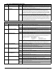
AC Failure Communication Delay (Minutes/Hours)
This value determines the delay before an AC Failure or AC Restoral is reported. The AC failure or restoral is still displayed immediately. Valid entries are from
000 to 255 minutes/hours.
NOTE: Selection of minutes or hours for the delay is set in section [382], Option 6.
NOTE: If AC Failure Communications Delay is programmed as 000, the AC Failure Trouble reporting code will be sent immediately*.
TLM Trouble Delay
The number of valid checks (10 second interval) required before a Telephone Line Trouble is generated is programmed here. Valid entries are 000-255 for Trou-
ble annunciation and transmission (LINKS) delays of 10 to 2550 Seconds (42.5 Minutes).
Test Transmission Cycle (Land Line)
NOTE:
This value determines the period between Test Transmissions for the Land Line. Valid entries are [000]-[255]. Whether this interval
is in minutes or days is determined on Section [702], Option 3.
*NOTE:
Do not use this section for central & remote fire applications
.