WARNING: Please refer to the System Installation Manual for information on limitations regarding product use and function and information on the limitations as to liability of the manufacturer. Installation Manual LCD55 O1Z32-433 NA DLS-3 v1.3 or higher version 4.
Table of Contents T A B L E O F C O N T E N T S Introduction 1 Section 1: Installation 2 1.1 1.2 1.3 1.4 1.5 2 2 2 3 3 Unpacking ................................................................................................................. Mounting .................................................................................................................... Wiring ...................................................................................................................
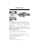
Introduction I N T R O D U C T I O N Introduction The LCD5501Z32-433 keypad combines a standard PC5132 receiver with an LCD5501Z keypad that presents system status using an LCD-style display with fixed messages. With the addition of the keypad, the control panel will now support up to 32 zones. The LCD5501Z32-433 is compatible with the following DSC security systems: • PC5010 (all versions) • PC5015 (all versions) • PC5020 (all versions) • PC1555 v2.3 and higher • Power608 v2.
Installation S E C T I O N 1 1.1 Unpacking The LCD5501Z32-433 package includes the following par ts: parts: • • • • • • • One LCD5501Z32-433 keypad One 5.6K Ohm resistor Four mounting screws One keypad inner door label One set of Fire, Auxiliary and Panic key labels One LCD5501Z User Sheet One LCD5501Z32-433 Installation Manual 1.2 Mounting You should mount the keypad where it is accessible to designated points of entry and exit.
I N S T A L L A T I O N 1.4 Applying Power Once all wiring is complete, apply power to the control panel: 1. Connect the battery leads to the battery. 2. Connect the AC transformer. For more information on control panel power specifications, see the control panel Installation Manual. NOTE: Do not connect the power until all wiring is complete. 1.
I N S T A L L A T I O N If both modules do not show on the keypad, one of the following conditions may be present: • the keypad is not connected properly to the Keybus • there is a problem with the Keybus wiring run • the keypad does not have enough power 1.6 Downloading This product has an integrated PC5132-433 v4.1 receiver. When downloading to this keypad, please select the PC5132-433 v4.1 file. DLS-3 v1.
Keypad Programming S E C T I O N 2 2.1 Programming the Keypad There are several programming options available for the LCD5501Z32-433 keypad. These are described below. Record all your programming choices in the programming worksheets included in this manual. Programming the LCD5501Z32-433 is similar to programming the rest of the system. When you are in the LCD5501Z32-433 programming sections, the keypad will display which options are turned on along the top of the display.
K E Y P A D P R O G R A M M I N G 2.4 Alarms Displayed While Armed Option You can disable the display of alarms on the keypad when the system is armed. The display of alarms is enabled by default. To disable the display of alarms when the system is armed, turn off section [6], option [5]: 1. Enter [*][8][Installer’s code] 2. Enter [000] to go to keypad programming 3. To turn the display of alarms on or off, enter section [6]. 4.
K E Y P A D P R O G R A M M I N G 1. Enter [*][8][Installer’s code] 2. Enter [000] to go to keypad programming 3. Enter section [6]. 4. To turn the options on or off, press [6] or [7]: [6] ON = Door Chime Enabled for Zone Openings OFF = Door Chime Disabled for Zone Openings [7] ON = Door Chime Enabled for Zone Closings OFF = Door Chime Disabled for Zone Closings 5. When you are finished, press [#] to exit.
Receiver Programming S E C T I O N 3 Enroll & Program Devices This section describes how to enroll and program: • wireless devices using zones (WLS904P, WLS906, WLS907, WLS912, WLS914 and WLS925L) • wireless keys (WLS909, WLS919) For more information on these devices, read the instruction sheet included with each device. 3.1 A Note about Electronic Serial Numbers An electronic serial number (ESN) is printed on the back of each wireless device.
E N R O L L & P R O G R A M D E V I C E S 5. The device is now enrolled on the system. Record the serial number and the assigned zone number in the programming worksheets in the back of this manual. 6. Continue with steps 3 - 5 until you have enrolled all wireless devices. 7. To exit press [#]. NOTE: The devices will not work properly until you complete zone and partition programming (see section 4). 3.
E N R O L L & P R O G R A M D E V I C E S 1. At a system keypad, enter [✱][8][Installer’s code]. 2. Enter programming section [804]. 3. Enter programming section [59] for keys assigned to partition 1, or [60] for keys assigned to partition 2. 4. For each of the 4 function buttons, enter the 2-digit number of the function you want to select. See the programming worksheets for a list of function key options. 5. Record your programming choices in the worksheets in the back of the manual. 6.
E N R O L L & P R O G R A M D E V I C E S 3.5 Deleting Wireless Devices To remove a wireless device from the system, follow the guideline for adding a wireless device. Program the ESN as [000000]. The wireless device for the zone will be removed. NOTE: You may need to remove power from the panel in order to clear troubles caused by deleted zones. Now that you have enrolled all the wireless devices, you will need to program the system to work properly with the devices.
Other Programming S E C T I O N 4 4.1 Program Zones and Partitions Now that you have enrolled the wireless devices, you should complete all zone programming on the system. Although the exact programming required varies depending on which control panel the LCD5501Z32-433 is connected to, you should check that the following programming areas are completed correctly for each wireless zone: • Enable zones and/or assign zones to one or more partitions (programming sections [201]-[209]).
O T H E R P R O G R A M M I N G To program the wireless supervisory window: 1. Enter [✱][8][Installer Code] to enter Installer Programming. 2. Enter [804] to enter into Receiver Programming. 3. Enter sections [81]. 4. Enter the time period for the supervisory window (8 to 24 hours). 5. To exit press [#]. Disable/Enable Zone Supervision All wireless zones have supervision enabled by default. To disable supervision for any zone, enter the following at any system keypad: 1.
O T H E R P R O G R A M M I N G To restore PC5132 to the settings, the O the T H E Rprogramming P R O G factory R Adefault M M I Nperform G following: 1. Enter [✱][8] [Installer’s Code]. 2. Enter programming section [996]. 3. Enter the Installer’s Code, followed by [996] again. Press [#]. The software for the receiver section will be restored to its factory default settings. 4. Press [#] to exit Installer Programming.
Testing & Mounting S E C T I O N 5 5.1 Test the placement of the WLS904P, WLS906, WLS907, WLS912, WLS914 and the WLS925L It is very important to test the proposed placement of each wireless device before it is mounted.
T E S T I N G & M O U N T I N G 5.2 Test WLS909 & WLS919 Reception The wireless key (WLS909) cannot be tested using the module placement test described above. To ensure that the LCD5501Z32-433 is receiving transmissions from these devices, conduct the following tests: WLS909/WLS919: Use the function keys to arm and disarm the system at several different points in the installation.
Additional Notes S E C T I O N 6 6.1 Trouble Conditions The control panel always watches for possible trouble conditions. If a trouble condition occurs, the keypad “Trouble” light will turn on and the keypad will beep. Press [✱][2] to display the trouble conditions. The following trouble conditions apply to the receiver portion (identified as the PC5132 by the panel) and/or any enrolled devices. For a description of all troubles, please see your system Installation Manual .
Tro u b l e s h o o t i n g S E C T I O N 7 1. When I enter the 2-digit zone number when adding a wireless device, the keypad gives me a long beep. You cannot enter ESNs unless the LCD5501Z32-433 is properly connected to the Keybus. See sections 1 & 3 for instructions on setting up and wiring the PC5132 module. 2. I have entered the ESN for the device but when I violate the device, the zone does not show open on the keypad.
Programming Worksheets S E C T I O N 8 [000] Keypad Programming 1. Enter [*][8][Installer’s code] 2. Enter [000] to go to keypad programming [0] Keypad Enrollment Valid entries are 01-18; e.g. enter [11] for partition 1, slot 1.
P R O G R A M M I N G W O R K S H E E T S [*] Door Chime Sound Programming 1. Enter [*][8][Installer’s code][*] 2. Enter 2-digit zone number [01] - [32], then select door chime sound option [1] - [4]. Repeat for each zone that is to sound a chime.
P R O G R A M M I N G W O R K S H E E T S [804] Wireless Expansion Programming • 6-digit entry is required. See Section 3.1 “A note on Electronic Serial Numbers” for details on programming 6-digit serial numbers. • When enrolling devices with 5-digit serial numbers on the LCD5501Z32-433, the first digit must be zero (0), followed by the 5-digit serial number (6-digits total). For example, to enter the serial number 42345 on a LCD5501Z32-433, enter “042345.
P R O G R A M M I N G W O R K S H E E T S Wireless Key Serial Numbers Default = 000000 [41] Key 01 l_____l_____l_____l_____l_____l_____l [49] Key 09 l_____l_____l_____l_____l_____l_____l [42] Key 02 l_____l_____l_____l_____l_____l_____l [50] Key 10 l_____l_____l_____l_____l_____l_____l [43] Key 03 l_____l_____l_____l_____l_____l_____l [51] Key 11 l_____l_____l_____l_____l_____l_____l [44] Key 04 l_____l_____l_____l_____l_____l_____l [52] Key 12 l_____l_____l_____l_____l_____l_____l [45] K
P R O G R A M M I N G W O R K S H E E T S Default = 00 Partition 1 Wireless Key Options [59] Function Key 1 l____l____l Function Key 2 l____l____l Partition 2 Wireless Key Options [60] Function Key 1 l____l____l Function Key 2 l____l____l Function Key 3 l____l____l Function Key 4 l____l____l Function Key 3 l____l____l Function Key 4 l____l____l Supervision [81] Wireless supervisory Window Default = 32 l____l____l wireless device window (x15min), valid entries are 32-96.
P R O G R A M M I N G W O R K S H E E T S [84] Zone Device Supervision Options (17-24) Default = ON Option ON Option OFF l________l Option 1 Zone 17 Supervision enabled Disabled l________l Option 2 Zone 18 Supervision enabled Disabled l________l Option 3 Zone 19 Supervision enabled Disabled l________l Option 4 Zone 20 Supervision enabled Disabled l________l Option 5 Zone 21 Supervision enabled Disabled l________l Option 6 Zone 22 Supervision enabled Disabled l________l Option 7
P R O G R A M M I N G W O R K S H E E T S [91] Wireless Keys (1-8) Partition Assignments Default = ON Option ON Option OFF l________l Option 1 Wireless Key 01 on partition 2 On partition 1 l________l Option 2 Wireless Key 02 on partition 2 On partition 1 l________l Option 3 Wireless Key 03 on partition 2 On partition 1 l________l Option 4 Wireless Key 04 on partition 2 On partition 1 l________l Option 5 Wireless Key 05 on partition 2 On partition 1 l________l Option 6 Wireless Key
Guidelines for Locating Smoke Detectors A P P E N D I X A Experience has shown that all hostile fires in family living units generate smoke to a greater or lesser extent. Experiments using typical fires in family living units indicate that detectable quantities of smoke precede detectable levels of heat in most cases. In existing homes, NFPA Standard 72 requires that a smoke detector be installed outside each sleeping area and on each additional story of the family unit.
LIMITED WARRANTY Digital Security Controls Ltd. warrants the original purchaser that for a period of twelve months from the date of purchase, the product shall be free of defects in materials and workmanship under normal use. During the warranty period, Digital Security Controls Ltd. shall, at its option, repair or replace any defective product upon return of the product to its factory, at no charge for labour and materials.
WARNING Please Read Carefully Note to Installers This warning contains vital information. As the only individual in contact with system users, it is your responsibility to bring each item in this warning to the attention of the users of this system. System Failures This system has been carefully designed to be as effective as possible. There are circumstances, however, involving fire, burglary, or other types of emergencies where it may not provide protection.
This device complies with RSS-210 of Industry Canada. Operation is subject to the following two conditions: (1) this device may not cause interference, and (2) this device must accept any interference, including interference that may cause undesired operation of the device. Ce dispositif satisfait aux exigences d’Industrie Canada, prescrites dans le document CNR-210.