WARNING This manual contains information on limitations regarding product use and function and information on the limitations as to liability of the manufacturer. The entire manual should be carefully read. Installation Manual PC1565 Software Version 2.3A DLS-3 v1.
WARNING Please Read Carefully N o te t o I n s t al le r s This warning contains vital information. As the only individual in contact with system users, it is your responsibility to bring each item in this warning to the attention of the users of this system. S ys te m Fa i lu r e s This system has been carefully designed to be as effective as possible. There are circumstances, however, involving fire, burglary, or other types of emergencies where it may not provide protection.
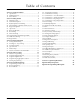
Ta ble of Contents Section 1: System Introduction 1 1.1 Specifications ........................................................................1 1.2 Additional Devices ..............................................................2 1.3 Out of the Box .......................................................................2 Section 2: Getting Started 3 2.1 Installation Steps ..................................................................3 2.2 Terminal Descriptions ..........................................
PC1565 Wiring Diagram COMPATIBLE SYSTEM KEYPADS PC5508Z LCD5500Z PC5509 LCD5501Z PC5516Z LCD5501Z32-433 PC5532Z PC1555RKZ ii
Section 1: System Introduction 1.1 Specifications Downloading Software Support • PC1565 v2.3 uses DLS-3 v1.3 and up.
1.2 Additional Devices In addition to the information below, see the back cover for a DSC module compatibility table. PC5132 Wireless Receiver The PC5132 Wireless Receiver module can be used to connect up to 32 fully supervised wireless devices (see the PC5132 Installation Manual for details.) PC5400 Printer Module The PC5400 Printer Module allows the panel to print out all events that occur on the system to any serial printer. The printout will contain the time, date and the event that occurred.
Section 2: Getting Started The following sections provide a thorough description of how to wire and configure devices and zones. 2.1 Installation Steps Read this section completely before you begin. Once you have an overall understanding of the installation process, carefully work through each step. Step 1: Create a Layout Draw a rough sketch of the building to get an idea of where all alarm detection devices, keypads and other modules are to be located.
Programmable Output Terminals – PGM1 and PGM2 Each PGM output is designed so that when activated by the panel, the terminal will switch to ground PGM1 can sink up to 300mA of current. Connect the positive side of the LED or buzzer to AUX+, the negative side to PGM1. If more than 300 mA of current are required, a relay must be used. PGM2 operates similarly to PGM1. However, PGM2 can only sink up to 50mA of current. Please study PGM wiring in the accompanying diagram.
G e t t i n g After assigning all keypads, perform a supervisory reset by entering section [902] in installer’s programming. The panel will now supervise all assigned keypads and enrolled modules on the system. How to Program Function Keys By default, the 5 function keys on each keypad are programmed as Stay Arm (03), Away Arm (04), Chime (06), Sensor Reset (14) and Quick Exit (16). You can change the function of each key on every keypad: 1.
The following chart shows zone status under certain conditions: Loop Resistance Loop Status 0Ω (shorted wire, loop shorted) Fault 5600Ω (contact closed) Secure Infinite (broken wire, loop open) Tamper 11200Ω (contact open) Violated End of Line Resistors. . . . . . . . . . . . . . . . . . Section [013]: [1] Double End of Line Resistors . . . . . . . . . . . Section [013]: [2] 2.9 Fire Zone Wiring 4-Wire Smoke Detectors All fire zones must be wired according to the following diagram: 2.
G e t t i n g S t a r t e d : 2 . 1 2 K e y p a d Z o ne s NOTE: Keypad zones do not support DEOL resistors. Assigning Keypad Zones When using keypad zone inputs, each input used must be assigned a zone number in Installer’s Programming. First, ensure that you have enrolled all installed keypads into the desired slots (See 2.5 “Keypad Assignment” ) Next, enter programming section [020] to assign the zones. There are eight programming locations in this section, one for each keypad slot.
Section 3: Keypad Commands Use any system keypad to enter commands and/or program the PC1565 security system. The LED keypad uses function and zone indicator lights to represent alarm functions and status. If you have a PC1555RKZ keypad, the System light acts as a Trouble, Memory, Program and Bypass indicator. Unlike other LED keypads, these conditions will only be represented by the System light.
K e y p a d Activate Stay/Away Zones If the system is armed in stay mode, the [*][1] command can be used to activate the stay/away zones. [*][2] Trouble Display The panel constantly monitors itself for several different trouble conditions. If a trouble condition is present, the Trouble (or System) light will be on and the keypad will beep twice every 10 seconds. The trouble beep can be silenced by pressing any key on any keypad.
[*][5] Programming Access Codes There are 37 access codes available to the user. They are: Access code (40) ..................... One master code Access codes (01)-(32)............ 32 general access codes Access codes (33)-(34)............ Two duress codes Access codes (41)-(42)............ Two supervisor codes All access codes have the ability to arm or disarm the system and can activate the PGM Outputs using the [*][7] commands. Access codes can be either four or six digits (See 5.
K e y p a d C o m m a n d s : 3 . 5 F u nc t io n K e y s press [#] to exit. This feature can be accessed on LED keypads by pressing and holding the [*] key. NOTE:On the PC1555RKZ keypad, use number keys 1 - 5 for the function keys. [*][7] Command Output Functions The user can activate programmable output functions using the [*][7][1-2] commands. The outputs may be activated when the system is either armed or disarmed. “Stay” – (03) Stay Arm The system will arm in the Stay mode (see 3.
[*][7][1] Command Output Option #1: A valid access code may need to be entered. [14] [*][7][2] Reset (Command Output Option #2): As described above. [15] For future use [16] [*][0] Quick Exit: As described above. [17] [*][1] Reactivate Stay/Away Zones [18] - [20] For future use [13] 3.
Section 4: How to Program The following section of the manual describes the Installer’s Programming function and how to program the various sections. NOTE: Read the following section of the manual very carefully before you begin programming. We also recommend filling out the Programming Worksheets section before you program the panel. For your reference, the corresponding programming sections for the functions listed are highlighted in text boxes such as this one. 4.
4.4 Programming Toggle Option Sections Some programming sections contain several toggle options. The panel will use zone lights 1 through 8 to indicate if the different options are enabled or disabled. Press the number corresponding to the option to turn it ON or OFF. Once all the toggle options have been selected correctly, press the [#] key to exit the section and save the changes. The Ready light will turn OFF and the Armed light will turn ON.
Section 5: Program Descriptions The following section explains the operation of all programmable features and options and provides a summary of all corresponding programming locations. 5.1 Programming Security Codes There are three codes which can be programmed by the installer in the Installer’s Programming function: the Master code, the Installer’s code, and a Maintenance code. All other access codes can be programmed through the [*][5] command.
NOTE:If a second Fire type zone is violated or if the Fire keys are pressed during the delay period, the panel will latch the alarm output and will immediately communicate the alarm. A violated Fire zone will be displayed on all keypads and can be delayed at any keypad. Typically this zone is used for latching smoke detectors. [08] Standard 24-hr Fire Zone NOTE:Do not wire Fire zones on keypad zone terminals if the DEOL supervision option is enabled for the panel (section [013], option [2]).
P r o g r a m D e s c r i p t i o n s : reporting code for the programmed Transmission Delay Period. (See 5.15 “Transmission Delay” ) • Wireless Zone – This attribute determines which zones are to have wireless devices. This allows the panel to generate a low battery trouble and zone supervisories for the wireless zones. NOTE: Any zone with the wireless attribute enabled will not cause an alarm for a fault condition when armed (or any time for 24-hr zones). Zone Attributes . . . . . . . . . . . .
NOTE:To use the Third Telephone Number, you must enable it in section [380], option [5], and program it in section [303]. NOTE:Telephone numbers can be up to 32 digits. This allows you to add special digits if required. To program the telephone number, enter the numbers 0 through 9 as required.
P r o g r a m D e s c r i p t i o n s : When Delinquency Follows Zone Activity (hours) is enabled, if there is no activity on zones in the system, the Delinquency Transmission Cycle Timer in Section [370] will begin counting in hours. When the counter reaches the programmed time, the panel will communicate the Delinquency reporting code to the central station, if programmed. If there is a closing or zone activity present on the system at any time, the counter will be reset.
If the SIA Sends Automatic Reporting Codes option is enabled, the panel will operate as follows: 1. If an event’s reporting code is programmed as [00], the panel will not attempt to call the central station. 2. If the reporting code for an event is programmed as anything from [01] to [FF], the panel will automatically generate the zone or access code number. If the SIA Sends Programmed Reporting Codes option is enabled, the panel will operate as follows: 1.
P r o g r a m PC-LINK was initiated. For more information on connecting the PC-LINK, refer to your “PC-LINK Download Kit Instruction Sheet”. NOTE: When a zone status upload is performed through PCLINK, the information uploaded may not be accurate. For more information, refer to your DLS-1 manual. Downloading can also be performed through the LINKS1000 cellular communicator if the telephone line is disconnected.
[4]......... Medical (Auxiliary Keys, Medical and Emergency Zones) [5]......... Supervisory (Supervisory, Freezer and Water Zones) [6]......... Priority (Gas, Heat, Sprinkler and 24-hr Latching Zones) [7]......... Holdup (Holdup zones) [8]......... Output Follows Timer (output will activate for the number of seconds programmed in the PGM Output Timer) / Output Latched NOTE:If attribute [8] is turned ON, attributes [1-7] must also be turned ON. PGM Output Timer. . . . . . . . . . . . . . . . . . . . . . .
P r o g r a m D e s c r i p t i o n s : [2] and [5] must be the same. This does not apply to outputs programmed as types [09] and [10]. PGM Output Attributes . . . . . . . . . . . . . . Section [141]-[142] 5.12 Telephone Line Monitor (TLM) When the TLM Enable option is selected, the panel will supervise the telephone line and will indicate a trouble condition if the telephone line is disconnected. If the TLM Enable option is ON, the panel will check the telephone line every 10 seconds.
If the [P] / Key is pressed and held for two seconds, the panel will immediately communicate the signal to central station. If [P] Key Audible Bell and Buzzer option is enabled, when a user presses the [P] / key, the keypad will beep three times and the panel will activate the alarm output until an access code is entered or the bell cut-off expires. If the option is disabled, the Panic alarm will be completely silent. Each LCD keypad may be programmed to have the [F], [A], & [P] keys enabled or disabled.
P r o g r a m there was an alarm during the armed period, the keypad will pulse for the entire entry delay to warn the user of the previous alarm. For commercial applications Bell Squawk on Entry Delay may be enabled. The panel will squawk the alarm output once every second until the entry delay expires or the system is disarmed. If the Bell Squawk During Auto-arm option is enabled, the bell will squawk once every 10 seconds for one minute during the Auto-arm pre-alert.
NOTE:The auto-arm cancellation code is not transmitted when a reset is required because a user has not cancelled the autoarming sequence. Keypad Tamper Enable. . . . . . . . . . . . . . . . Section [016]: [8] General System Tamper and Tamper Restoral Reporting Codes . . . . . . . . . . . . . . . . . Section [338] System Tampers Req. Installer Reset . . . . . Section [701]: [4] NOTE: After enabling keypad tampers, it is recommended to tamper and restore all keypads to ensure proper functioning. 5.
P r o g r a m NOTE:If the Auto-arm time is set for 23:59, any change to the Clock Adjust option will directly affect the Auto-arm pre-alert time. Clock Adjust . . . . . . . . . . . . . . . . . . . . . . . . . . . Section [700] 5.29 Timebase In cases of unstable AC power input you can use the internal crystal to keep a more accurate timebase by enabling the Timebase is Internal Crystal option.
S e ct i on 6 : Prog rammi ng Works he e ts For the Record Customer: _______________________________________________________________________________________________________ Address: ________________________________________________________________________________________________________ Telephone: ___________________________________________ Installation Date: ___________________________________________ Installer’s Code: _________________________________________________________________________________________
P r o g r a m m i n g W o r k s h e e t s Zone Programming Summary Zone programming can be found in sections [001] - [004], [101] - [132], [020] and [202] - [205]. Use this area to record a summary of your zone programming. Refer to Appendix B: “Programming LCD Keypads”, for instructions on programming zone labels.
Keypad Programming [000] Keypad Enrollment (Section 2.5 “Keypad Assignment”) NOTE: This must be done at each keypad requiring programming. [0] Slot [Valid entries are 11-18; i.e. enter [11] for slot 1, [12] for slot 2, etc.
P r o g r a m m i n g W o r k s h e e t s [002] Zone 9-16 Definitions (Section 5.2 “Zone Programming”) Default Default 00 I_______I_______I Zone 9 00 I_______I_______I Zone 13 00 I_______I_______I Zone 10 00 I_______I_______I Zone 14 00 I_______I_______I Zone 11 00 I_______I_______I Zone 15 00 I_______I_______I Zone 12 00 I_______I_______I Zone 16 [003] Zone 17-24 Definitions (Section 5.
[012] Keypad Lockout Options (Section 5.21 “Keypad Lockout Options”) NOTE:If Keypad Lockout is active, the panel cannot be disarmed with a keyswitch. Default 000 I_______I_______I_______I Number of Invalid Codes Before Lockout (001-255 codes) 000 I_______I_______I_______I Lockout Duration (001-255 minutes) [013] First System Option Code Default Option ON 1 Normally Closed Loops OFF I________I Off End-of-Line Resistors Section 2.
P r o g r a m m i n g [017] Fifth System Option Code Default Option ON 1 WLS Key Does Not Use Access Codes* ON I________I OFF I________I 2-7 OFF I________I 8 Off WLS Key Uses Access Codes W o r k s h e e t s Section 5.17 For future use Squawk on Away Arming/Disarming OnlyBell Squawk on all Arming/Disarming 5.17 *This option must be enabled when using a PC5132 v2.1 or earlier. [020] Keypad Zone Assignments (Section 2.12 “Keypad Zones”) NOTE:Only one keypad may be assigned to a zone.
Advanced System Programming Zone Attributes (Section 5.3 “Zone Attributes”) Zone Attribute Defaults (Y = Option ON; N = Option OFF): Attribute: ON OFF Zone Type: 00 Null Zone 01 Delay 1 02 Delay 2 03 Instant 04 Interior 05 Int. Stay/Away 06 Dly. Stay/Away 07 Dly. 24-hr Fire (Hardw.) 08 Stand. 24-hr Fire (Hardw.) 09 24-hr Superv. 10 24-hr Superv.
P r o g r a m m i n g W o r k s h e e t s [116] 16 ( ) I________I I________| I________| I________| I________| I________| I________| I________I [117] 17 ( ) I________I I________| I________| I________| I________| I________| I________| I________I [118] 18 ( ) I________I I________| I________| I________| I________| I________| I________| I________I [119] 19 ( ) I________I I________| I________| I________| I________| I________| I________| I________I [120] 20 ( )
Section PGM # [141] 1 Output Type* ( ) 1 2 3 4 5 6 7 8 I________I I________| I________| I________| I________| I________| I________| I________I [142] ( I________I I________| I________| I________| I________| I________| I________| I________I 2 ) *Record here based on programming in [009]. [160] Maximum Dialing Attempts to Each Telephone Number (Section 5.5 “Communicator – Dialing”) Default: 003 I_______I_______I_______I Valid entries are 001-015 attempts (do not enter 000).
P r o g r a m m i n g Alarm Reporting Codes, Zones 1-32 (Section 5.
[338] Miscellaneous Tamper Reporting Codes (Section 5.8 “Communicator – Reporting Codes” & Appendix A) I___4__I___5____I 1. General System Tamper I___4__I___5____I 2. General System Tamper Rest. I___2__I___1____I 3. Keypad Lockout Closing (Arming) Reporting Codes, Access Codes 1-32 (Section 5.
P r o g r a m m i n g W o r k s h e e t s [351] Miscellaneous Maintenance Reporting Codes (Section 5.8 “Communicator – Reporting Codes” & Appendix A) I___5___I___4____I 1. Telephone Number 1 FTC Restore I___1___I___2____I 5. DLS Lead OUT I___5___I___4____I 2. Telephone Number 2 FTC Restore I___7___I___2____I 6. Zone Fault Alarm I___F___I___F____I 3. Event Buffer 75% Full Since Last Upload I___7___I___2____I 7. Zone Fault Restore I___1___I___1____I 4. DLS Lead IN I___F___I___F____I 8.
[368] System Test Transmissions Communicator Call Directions (Section 5.5 “Communicator – Dialing”) Default Option ON OFF ON I________I 1 1st Telephone Number Disabled OFF I________I 2 2nd Telephone Number OFF I________I 3 1st Telephone Number (via LINKS) Disabled OFF I________I 4 2nd Telephone Number (via LINKS) Disabled Disabled OFF I________I 5-8 For future use NOTE:The LINKS1000 backup call directions will only back up their respective telephone numbers.
P r o g r a m m i n g W o r k s h e e t s [390] LINKS Preamble (First Telephone Number) (Section 5.26 “LINKS1000 Cellular Communicator”) Default: FFFF I_______I_______I_______I_______I (Program all unused digits with Hex F) [391] LINKS Preamble (Second Telephone Number) (Section 5.26 “LINKS1000 Cellular Communicator”) Default: FFFF I_______I_______I_______I_______I (Program all unused digits with Hex F) [392] LINKS Preamble (Third Telephone Number) (Section 5.
[702] Second International Options Code Default Option ON 1 Pulse Dialing Make/Break Ratio is 33/67 ON I_______I Off Pulse Dialing Make/Break Ratio is 40/60 ON I_______I 2 Force Dialing enabled Force Dialing disabled 5.5 OFF I_______I 3 Land line Test Transmission in minutes Land line Test Transmission in days 5.14 OFF I_______I 4 1600 Hz Handshake Standard Handshake 5.9 OFF I_______I 5 ID Tone enabled ID Tone disabled 5.5 OFF I_______I 6 2100 HZ ID Tone 1300 Hz ID Tone 5.
Appendix A: Reporting Codes The following tables contain Contact ID and Automatic SIA format reporting codes. For more information on reporting code formats and notes about individual reporting codes, see sections 5.8 “Communicator – Reporting Codes” and 5.9 “Communicator – Reporting Formats”. Contact ID The first digit (in parentheses) will automatically be sent by the control. The second two digits are programmed to indicate specific information about the signal.
Section # Reporting Code Code Sent When... [349-350] AC Line Trouble/Rest. [349-350] Main Bell Trouble/Rest. [349-350] [349-350] Fire Trouble/Rest. Auxiliary Power Trouble/ Rest. TLM Failure AC power to control panel is disconnected or interrupted/AC power restored (Both codes follow AC Failure Comm. Delay.
Appendix B: Programming LCD Keypads If you have an LCD5500Z Keypad, additional programming is required for proper operation. The following is a description of the available programming options and their accompanying programming sections: How to Enter LCD Programming Follow the programming procedure as outlined in Section 4 by pressing [*][8][Installer’s Code]. Press the [*] key. Enter the two digit Section number to be programmed.
[61] Second User Display Mask Default Option ON OFF I_______I 1 Installer Programming Prompt ON Installer Programming Prompt OFF OFF I_______I 2 Stay Arm Prompt ON Stay Arm Prompt OFF ON ON I_______I 3 Quick Arm Prompt ON Quick Arm Prompt OFF I_______I 4 Interior Arm Prompt ON Interior Arm Prompt OFF ON I_______I 5 Quick Exit Prompt ON Quick Exit Prompt OFF OFF ON I_______I 6 View Event Buffer Prompt ON View Event Buffer Prompt OFF I_______I 7-8 For future use OFF [62] Third User Display Mask Default Option
PC1565 Module Compatibility Module Classic Escort (VPM-1) Escort5580 PC-16 Out PC5204 PC5208 PC5108 PC5108L PC5132 v1.X PC5132 v2.X PC5132 v3.X PC5506 PC55XX PC55XXZ PC5509 LCD5500 v1.X LCD5500Z v2.X LCD600 LED615 SL-XX PC1500RK PC1555RKZ PC5908 PC5928 PC5400 Printer Module v1.X to v2.1 PC5400 Printer Module v2.