WARNING This manual contains information on limitations regarding product use and function and information on the limitations as to liability of the manufacturer. The entire manual should be carefully read. This panel will not operate if installed outside of North America. See section 1.1 for details. Installation Manual PC1555MX Software Version 2.3 DLS-3 v1.
WARNING Please Read Carefully No t e t o I n s ta l le r s This warning contains vital information. As the only individual in contact with system users, it is your responsibility to bring each item in this warning to the attention of the users of this system. S y st e m F a i lu r e s This system has been carefully designed to be as effective as possible. There are circumstances, however, involving fire, burglary, or other types of emergencies where it may not provide protection.
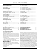
Ta ble of Contents Section 1: System Introduction 1 1.1 Specifications ........................................................................1 1.2 Additional Devices ..............................................................2 1.3 Out of the Box .......................................................................3 Section 2: Getting Started 4 2.1 Installation Steps ..................................................................4 2.2 Terminal Descriptions ..........................................
P C 1 5 5 5 M X Wir i n g D i a g r a m LCD5500Z LCD5501Z PC1555RKZ LCD5501Z32 PC5502Z2 ii PC5506 PC5508Z PC5516Z PC5532Z SL-8
Section 1: System Introduction 1.1 Specifications Downloading Software Support • PC1555MX v2.3 uses DLS-3 v1.3 and higher.
• Added Keybus fault protection: clock and data outputs have been programmed to withstand shorts to +12v to prevent control panel damage 1.2 Additional Devices In addition to the information below, see the back cover for a DSC module compatibility table. PC5132 Wireless Receiver The PC5132 wireless receiver can be used to connect up to 32 wireless devices to the system. All devices are fully supervised which use standard alkaline or lithium batteries.
PC55BP1 Backplate This backplate is to be used when an audio station is to be located next to a keypad. Dimensions 208mm x 115mm x 18mm / 8.2” x 4.5” x 0.25” approximately. PC55BP2 Backplate This backplate is to be used when an audio station is to be located next to a keypad. In addition the backplate will allow you to mount a PC5208 8 low current output module. Dimensions 208mm x 115mm x 18mm / 8.2” x 4.5” x 0.7” approximately. 1.
Section 2: Getting Started The following sections provide a thorough description of how to wire and configure devices and zones. 2.1 Installation Steps Read this section completely before you begin. Once you have an overall understanding of the installation process, carefully work through each step. Step 1: Create a Layout Draw a rough sketch of the building to get an idea of where all alarm detection devices, keypads and other modules are to be located.
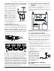
G e t t i n g S t a r t e d : 2 . 3 W ir e Programmable Output Terminals – PGM1 and PGM2 Each PGM output is designed so that when activated by the panel, the terminal will switch to ground PGM1 can sink up to 50mA of current. Connect the positive side of the LED or buzzer to AUX+, the negative side to PGM1. PGM2 operates similarly to PGM1. However, PGM2 can sink up to 300mA of current. If more than 300mA of current are required, a relay must be used.
sion devices must not be exceeded. Use the data presented below to ensure that no part of the system is overloaded and that all parts can function properly. PC1555MX (12 VDC) AUX+: ........ 550mA: Subtract the listed rating for each keypad, expansion module and accessory connected to AUX+ or Keybus. BELL: ......... 700mA continuous rating; 3.0A short term. Available only with standby battery connected.
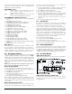
G e t t i n g S t a r t e d : 2. 10 2 4 - H r A u x il ia r y I n pu t W ir in g ( P G M 2 ) NOTE: See the Wiring Diagram Compatibility Chart for a list of compatible 2-wire smoke detectors. NOTE: If PGM2 is programmed for 2-wire smoke support, the connector JP1 on the main board must be removed. NOTE: 2-wire smoke detectors are not supported on the 50/50 version of the panel. 2.
2.12 LINKS Zone Wiring LINKS Support When using the LINKS1000 cellular communicator, connect the LINKS to the main panel according to the following diagram: the control panel: the red wire to R, the black to B, the yellow to Y and the green to G. To connect the zone, run one wire to the Z terminal and the other to B. For powered devices, use red and black to supply power to the device. Run the red wire to the R (positive) terminal and the black wire to the B (negative) terminal.
Section 3: Keypad Commands Use any system keypad to enter commands and/or program the PC1555MX security system. The LED keypad uses function and zone indicator lights to represent alarm functions and status. The LCD keypad provides a written description on the liquid crystal display and uses function indicator lights to communicate alarm status to the user.
on any keypad. If Bell Squawk on Trouble is enabled (section [014], option [5]), the bell will squawk every 10 seconds when a trouble condition is present. To view trouble conditions from an LED or a Fixed Message LCD keypad: 1. Press [*][2]. 2. The keypad will flash the Trouble light. The zone indicator lights corresponding to the present trouble conditions will be ON. Light 1 When using an LCD keypad, the trouble conditions will be listed on the display.
K e y p a d C o m m a n d s : 3. 4 [ *] C om m a n ds vated. (see 5.3“Zone Attributes” ) If the door chime feature is enabled, the keypad will emit five short beeps whenever a chime zone is activated. Designated entry/exit doors are often defined as chime zones. The feature can be turned on or off while the system is armed or disarmed.
Keypad Sounder Control You can select from 21 different keypad tones. Use the arrow keys (< >) to scroll to the desired keypad sound level and press [#] to exit. This feature can be accessed on LED keypads by pressing and holding the [*] key. [*][7] Command Output Functions The user can activate programmable output functions using the [*][7][1-4] commands. The outputs can be activated when the system is either armed or disarmed.
General Voice Prompt Help: This feature can only be programmed if the Escort5580(TC) and PC5928 audio matrix module or PC5936 audio interface module are being used. The intercoms will perform a Help page. The user must then press the Page/Answer button on any intercom station to begin the help session with the Escort. [16] [*][0] Quick Exit: As described above.
Section 4: How to Program The following section of the manual describes installer programming. NOTE: Read the following section of the manual very carefully before you begin programming. We also recommend filling out the Programming Worksheets section before you program the panel. For your reference, the corresponding programming sections for the functions listed are highlighted in text boxes like this one. 4.
4.4 Programming Toggle Option Sections Some programming sections contain several toggle options. The panel will use zone lights 1 through 8 to indicate if the different options are enabled or disabled. Press the number corresponding to the option to turn it ON or OFF. Once all the toggle options have been selected correctly, press the [#] key to exit the section and save the changes. The Ready light will turn OFF and the Armed light will turn ON.
Section 5: Program Descriptions The following section explains the operation of all programmable features and options and provides a summary of all corresponding programming locations. 5.1 Programming Security Codes There are three codes which can be programmed by the installer in the installer programming function: the Master Code, the Installer’s Code, and a Maintenance Code. All other access codes can be programmed through the [*][5] command.
P r o g r a m A violated Fire zone will be displayed on all keypads and can be delayed at any keypad. Typically this zone is used for latching smoke detectors. [08] Standard 24 Hour Fire Zone NOTE: Do not wire Fire zones on keypad zone terminals if the DEOL supervision option is enabled for the panel (section [013], Option [2]). When this zone is violated, the panel will immediately latch the alarm output and communicate to the central station.
erate a low battery trouble and zone supervisories for the wireless zones. NOTE: Any zone with the wireless attribute enabled will not cause an alarm for a fault condition when armed (or any time for 24 hour zones). 5.6 Communicator – Account Numbers The account number is used by the central station to distinguish between panels. There are two account numbers programmable for the PC1555MX. Zone Attributes . . . . . . . . . . . Sections [101] - [132]: [1] - [8] First Account Code (4 digits) . . . . . .
P r o g r a m D e s c r i p t i o n s : tact ID and SIA format codes, please see Appendix A: “Reporting Codes” . NOTE: Do not use the digit C in a reporting code when using Pager Format. In most cases, the digit C will be interpreted as a [#], which will terminate the page before it has finished. 5. 9 C o m m un ic a t or – R e p o rt i ng F or m a t s The AC Failure Trouble Restoral reporting code follows the AC failure communication delay as well.
NOTE: Do not program the 2nd telephone number to use Contact ID or SIA reporting code formats (section [360]) if Automatic reporting codes are selected for either Contact ID or SIA (section [381]). Communicator Format Options . . . . . . . . . . . . . Section [360] Communicator Call Directions. . . . . . .
P r o g r a m D e s c r i p t i o n s : 5 . 1 0 D o w n l oa d in g generated if the panel detects a busy tone on all dialing attempts, or if no dial tone is detected on all dialing attempts. The pager format will not cause any form of ringback. NOTE: The Pager format cannot be used with the LINKS1000 cellular communicator. on connecting the PC-Link, refer to your “PC-Link Download Kit Instruction Sheet”.
NOTE: For the 2-wire smoke option to work, connector JP1 must be removed from the PC1555MX control board. NOTE: 2-wire smoke detectors use PGM2 as a supervised input with a 2200Ω end-of-line resistor. A trouble condition will be generated if an open condition is detected between PGM2 and Aux+ . NOTE: For option [04], 2-wire smoke, do not change the PGM output attributes from the default settings. [05] Armed Status When the system is armed, the PGM output will activate at the beginning of the exit delay.
P r o g r a m D e s c r i p t i o n s : [18] Stay Armed Status When the system is armed in the Stay mode, this PGM output will activate at the beginning of the exit delay. The output deactivates when the panel is disarmed. [19] [*][7][1] Command Output Option #1 [20] [*][7][2] Command Output Option #2 [21] [*][7][3] Command Output Option #3 [22] [*][7][4] Command Output Option #4 These outputs are user-initiated by entering [*][7][1-4] at any keypad.
If Fire Bell Continuous is enabled, the alarm output will sound until a code is entered. If disabled, the alarm will sound until a code is entered or the bell cut-off time has expired. Bell Cut-off. . . . . . . . . . . . . . . . . . . . . . . . . . . . . Section [005] Bell Circuit Trouble Reporting Code . . . . . . . . . Section [349] Bell Circuit Trouble Restoral Reporting Code . . Section [350] Temporal Three Fire Signal Enable/Disable Section [013]: [8] Fire Bell Continuous . . . . . . . . . . . . . . .
P r o g r a m D e s c r i p t i o n s : 5 . 1 8 E n t r y / E x it D e l a y O pt i o ns If you enable the WLS Key Does Not Use Access Codes option, the disarm button will work on wireless keys which have not been assigned access codes. Wireless keys can only be assigned access codes when used with PC5132 v3.0 or higher or with PC5102 1.0 and higher. To prevent disarming by wireless keys which don’t have access codes, disable this option.
NOTE: The Invalid Code Counter will be reset every hour. 5.26 LINKS1000 Cellular Communicator To disable the keypad lockout option, program the Number of Invalid Codes Before Lockout as [000]. NOTE: If Keypad Lockout is active, the panel CANNOT be armed / disarmed with a keyswitch.
LINKS Preamble (First Telephone Number) . . . Section [390] LINKS Preamble (Second Telephone Number) Section [391] LINKS Preamble (Third Telephone Number) . . Section [392] LINKS Preamble (Downloading Telephone Number) . . . . . . . . . Section [490] Communicator Call Direction Options . . . Section [361]-[368] Call LINKS as well as Land Line . . . . . . . . Section [380]: [7] LINKS Special Preamble . . . . . . . . . . . . . . . . .
S e ct i on 6 : Prog rammi ng Works he e ts For the Record Customer: _______________________________________________________________________________________________________ Address: ________________________________________________________________________________________________________ Telephone: ___________________________________________ Installation Date: ___________________________________________ Installer’s Code: _________________________________________________________________________________________
P r o g r a m m i n g W o r k s h e e t s Zone Programming Summary Zone programming can be found in sections [001] - [004], [101] - [132], [020] and [202] - [205]. Use this area to record a summary of your zone programming. Refer to Appendix B: “Programming LCD Keypads” , for instructions on programming zone labels.
Keypad Programming [000] Keypad Enrollment (Section 2.6 “Keypad Assignment” ) NOTE: This must be done at each keypad requiring programming. [0] Slot [Valid entries are 11-18; i.e. enter [11] for slot 1, [12] for slot 2, etc.
P r o g r a m m i n g W o r k s h e e t s [002] Zone 9-16 Definitions (Section 5.2 “Zone Programming” ) Default Default 00 I_______I_______I Zone 9 00 I_______I_______I Zone 13 00 I_______I_______I Zone 10 00 I_______I_______I Zone 14 00 I_______I_______I Zone 11 00 I_______I_______I Zone 15 00 I_______I_______I Zone 12 00 I_______I_______I Zone 16 [003] Zone 17-24 Definitions (Section 5.
[010] PC5208 PGM Output Programming (PGM 3-10) (Section 5.11 “PGM Output Options” ) Default Default 01 I_______I_______I PGM 3 01 I_______I_______I PGM 7 01 I_______I_______I PGM 4 01 I_______I_______I PGM 8 01 I_______I_______I PGM 5 01 I_______I_______I PGM 9 01 I_______I_______I PGM 6 01 I_______I_______I PGM 10 Program PGM Option Attributes in sections [143] - [150]. [011] PC5204 PGM Output Programming (PGM 11-14) (Section 5.
P r o g r a m m i n g [015] Third System Option Code Default Option ON 1 Fire Keys Enabled ON I________I W o r k s h e e t s Off Fire Keys Disabled Section 5.16 OFF I________I 2 OFF I________I 3 ON* I________I 4 OFF I________I 5 Code Required For Bypassing No Code Required 3.4 OFF I________I 6 Master Code Not Changeable Master Code Changeable 5.1 ON I________I 7 TLM Enabled TLM Disabled 5.12 OFF I________I 8 TLM Audible (Bell) When Armed TLM Trouble Beeps When Armed 5.
Advanced System Programming Zone Attributes (Section 5.3 “Zone Attributes” ) Zone Attribute Defaults (Y = Option ON; N = Option OFF): Attribute: ON OFF Zone Type: 00 Null Zone 01 Delay 1 02 Delay 2 03 Instant 04 Interior 05 Int. Stay/Away 06 Dly. Stay/Away 07 Dly. 24hr Fire (Hardw.) 08 Stand. 24hr Fire (Hardw.) 09 24hr Superv. 10 24hr Superv.
P r o g r a m m i n g W o r k s h e e t s [116] 16 ( ) I________I I________| I________| I________| I________| I________| I________| I________I [117] 17 ( ) I________I I________| I________| I________| I________| I________| I________| I________I [118] 18 ( ) I________I I________| I________| I________| I________| I________| I________| I________I [119] 19 ( ) I________I I________| I________| I________| I________| I________| I________| I________I [120] 20 ( )
Section PGM # Main Board [141] 1 Output Type* 1 2 3 4 5 6 7 8 ( ) I________I I________| I________| I________| I________| I________| I________| I________I [142] 2 ( ) I________I I________| I________| I________| I________| I________| I________| I________I PC5208 [143] [144] 3 ( ) I________I I________| I________| I________| I________| I________| I________| I________I 4 ( ) I________I I________| I________| I________| I________| I________| I________| I_______
P r o g r a m m i n g W o r k s h e e t s [301] First Telephone Number (32 Digits) (Section 5.7 “Communicator – Telephone Numbers” ) I_____I_____I_____I_____I_____I_____I_____I_____I_____I_____I_____I_____I_____I_____I_____I_____I_____I_____I_____I_____I_____I_____I_____I_____I_____I_____I_____I_____I_____I_____I_____I_____I [302] Second Telephone Number (32 Digits) (Section 5.
Tamper Restoral Reporting Codes, Zones 1-8 (Section 5.
P r o g r a m m i n g W o r k s h e e t s [350] Maintenance Restoral Reporting Codes (Section 5.8 “Communicator – Reporting Codes” & Appendix A) I_______I_______I 1. Battery Trouble Restoral I_______I_______I 5. Auxiliary Power Supply Trouble Restoral I_______I_______I 2. AC Failure Trouble Restoral I_______I_______I 6. TLM Restoral I_______I_______I 3. Bell Circuit Trouble Restoral I_______I_______I 7. General System Trouble Restore I_______I_______I 4.
[367] System Maintenance Alarm/Restore Communicator Call Directions (Section 5.5 “Communicator – Dialing” ) Default Option ON OFF ON I________I 1 1st Telephone Number Disabled OFF I________I 2 2nd Telephone Number OFF I________I 3 1st Telephone Number (via LINKS) Disabled OFF I________I 4 2nd Telephone Number (via LINKS) Disabled OFF I________I 5-8 Disabled For Future Use [368] System Test Transmissions Communicator Call Directions (Section 5.
P r o g r a m m i n g [381] Second Communicator Option Code Default Option ON 1 Open After Alarm Kypd Ringback Enabled OFF I_______I W o r k s h e e t s OFF Section Open After Alrm Kypd Ringback Disabled 5.17 OFF I_______I 2 Open After Alarm Bell Ringback Enabled Open After Alrm Bell Ringback Disabled 5.17 OFF I_______I 3 SIA Sends Programmed Rep. Codes SIA Sends Automatic Rep. Codes 5.9 OFF I_______I 4 Closing Confirmation Enabled Closing Confirmation Disabled 5.
[804] PC5132 Wireless Expansion Programming Please refer to your PC5102/PC5132 Installation Manual for programming locations and instructions. NOTE: The LINKS2X50 module has not been investigated by UL. Special Installer Functions [901] Installer Walk Test Mode Enable / Disable (Section 5.30 “Walk Test (Installer)” ) [902] Module Supervision Reset (Section 2.8 “Removing Modules” ) [903] Module Supervision Field (Section 2.
Appendix A: Reporting Codes The following tables contain Contact ID and Automatic SIA format reporting codes. For more information on reporting code formats and notes about individual reporting codes, see sections 5.8 “Communicator – Reporting Codes” and 5.9 “Communicator – Reporting Formats” . Contact ID The first digit (in parentheses) will automatically be sent by the control panel. The second two digits are programmed to indicate specific information about the signal.
Section # Reporting Code Code Sent When... [349-350] AC Line Trouble/Rest. [349-350] Main Bell Trouble/Rest. [349-350] [349-350] [349] Fire Trouble/Rest. Auxiliary Power Trouble/ Rest. TLM Failure AC power to control panel is disconnected or interrupted/AC power restored (both codes follow AC Failure Comm. Delay.
Appendix B: Programming LCD Keypads If you have an LCD5500Z keypad, additional programming is required for proper operation. The following is a description of the available programming options and their accompanying programming sections: How to Enter LCD Programming Follow the programming procedure as outlined in Section 4 by pressing [*][8][Installer’s Code]. Press the [*] key. Enter the two digit section number to be programmed.
[61] Second User Display Mask Default Option ON OFF I_______I 1 Installer Programming Prompt ON Installer Programming Prompt OFF OFF I_______I 2 Stay Arm Prompt ON Stay Arm Prompt OFF ON ON I_______I 3 Quick Arm Prompt ON Quick Arm Prompt OFF I_______I 4 Interior Arm Prompt ON Interior Arm Prompt OFF ON I_______I 5 Quick Exit Prompt ON Quick Exit Prompt OFF OFF ON I_______I 6 View Event Buffer Prompt ON View Event Buffer Prompt OFF I_______I 7 For Future Use OFF I_______I 8 Music Input ON Music Input OFF OF
P r o g r a m m i n g L C D K e y p a d s : [68] Sixth User Display Mask Default Option ON OFF I_______I 1 Occupancy Mode Auxiliary Prompt ON OFF I_______I 2 Occupancy Mode Day Prompt ON OFF I_______I 3 Occupancy Mode Away Prompt ON OFF I_______I 4 Occupancy Mode Night Prompt ON OFF I_______I 5-8 For Future Use [97] View Software Version [98] Initiate Global Label Broadcast 5.
PC1555MX Module Compatibility Module Compatible? Classic Escort (VPM-1) DLM-1 DLM-4 v1.x DLM-4 v1.0L DLM-7 Escort5580(TC) LCD5500 v1.X LCD5500Z v2.X LCD5501Z PC5502Z2 LCD600 LED615 Links1000 Links2150 Links2450 PC-16 Out PC1500RK PC1555RKZ PC5102 PC5108 PC5108L PC5132 v1.X PC5132 v2.X PC5132 v3.X PC5200 PC5204 PC5208 PC5320 PC5400 Printer Module v2.2 PC5400 Printer Module v1.X to v2.1 PC5400 Printer Module v2.