Installation Manual WITH WARNING This manual contains information on limitations regarding product use and function and information on the limitations as to liability of the manufacturer. The entire manual should be carefully read. PC5O15 Version 2.2 DLS-3 version 1.
LIMITED WARRANTY Digital Security Controls Ltd. warrants the original purchaser that for a period of twelve months from the date of purchase, the product shall be free of defects in materials and workmanship under normal use. During the warranty period, Digital Security Controls Ltd. shall, at its option, repair or replace any defective product upon return of the product to its factory, at no charge for labour and materials.
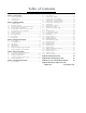
Table of Contents Section 1: Introduction 1.1 1.2 1.3 PC5015 Specifications ......................................................... 1 Additional Devices ............................................................... 2 Out of the Box ...................................................................... 4 Section 2: Getting Started 2.1 2.2 2.3 2.4 2.5 2.6 2.7 2.8 2.9 2.10 2.11 Installation Steps .................................................................. 5 Terminal Descriptions .................
System Introduction S 1.
S Y S T E M I N T R False Alarm Prevention Features • Audible Exit Delay • Audible Exit Fault • Quick Exit • Swinger Shutdown • Cross Zone Alarm • Burglary-verified timer • Communication Delay • Rotating Keypress Buffer O D U C T I O N • Urgency on Entry Delay • Recent Closing Transmission • Double Hit Timer Additional Features • Auto Arm by Partition at Specified Time each day of the week • Keypad Activated Alarm Output and Communicator Test • Keypad Lockout • Audio Capability using the
S Y S T E M I N T R O D U C T I O N 1.2.4 PC5200/PC5204 Power Supply Output Module The PC5200 and PC5204 can provide up to 1 Amp of additional power for modules or devices connected to the control panel. The PC5204 module requires a 16.5 volt AC 40 VA transformer and 4 AH battery. In addition, the module provides 4 programmable high current voltage outputs (see PC5204 Installation Instructions for details). 1.2.
S 1.2.11 Y S T E M I N T R O D U C T I O N PC5700 Fire Module This is a zone expansion module with four general purpose zone inputs, two Class A supervisory waterflow zone inputs, ground fault detection and dual-supervised telephone line inputs. 1.2.12 Cabinets Several different cabinets are available for the PC5015 modules. They are as follows: PC500C Control panel enclosure (Recommended use: Household Fire & Burglary) Dimensions 203.5mm x 229mm x 78mm / 8.0” x 9.0” x 3.
Getting Started S E C T I O N 2 The following sections provide a complete description of how to wire and configure devices and zones. 2.1 Installation Steps The following steps are provided to assist with the installation of the panel. It is suggested that you read over this section briefly to get an overall understanding of the order of installation. Once this is done carefully work through each step.
G E T T I N G S T A R T E D Auxiliary Power Terminals - AUX+ and GND These terminals provide up to 550 mA of additional current at 12 VDC for devices requiring power. Connect the positive side of any device requiring power to the AUX+ terminal, the negative side to GND. The AUX output is protected; if too much current is drawn from these terminals (wiring short) the panel will temporarily shut off the output, until the problem is corrected.
G E T T I N G S T A R T E D Connect the PC5015 and modules that use the telephone line(s) in the following order: For example, if you are installing a PC5015 with a LINKS1000 and a PC5928 Intercom module, connect the incoming line to the LINKS1000, then from the LINKS1000 to the PC5015, then from the PC5015 to the PC5928 Intercom and then from the PC5928 to the house telephones For pr oper operation ther e must be no other telephone equipment connected between the contr ol panel proper there
G E T T I N G S T A R T E D BELL: 700 mA. Continuous Rating. 3.0 A. Short Term. Available only with stand-by battery connected. • PC5200/5204 VAUX:1.0 A. Continuous Rating. Subtract for each device connected. 3.0 A. Short Term. Available only with stand-by battery connected. • PC5208 VAUX: 250 mA. Subtract for each device connected. Subtract the total load on this terminal from the PC5015 VAUX/Keybus output. • PC5108 VAUX: 100 mA. Subtract for each device connected.
G 2.7 E T T I N G S T A R T E D Keypad Assignment There are 8 available addresses for keypads. The LED, LCD5501Z and the LCD5501Z32-433 keypads by default are assigned to address 1 while the LCD5500(Z) is assigned by default to address 8. Keypads can each be assigned to a different address (1 to 8) which offers two advantages. The panel can supervise the keypad connection to indicate a trouble condition if it is removed.
G 2.9 E T T I N G S T A R T E D Removing Modules If a module is no longer required on the system the panel must be told to no longer supervise the module. To do this remove the module from the Keybus and perform the Enable supervision function again (See Section 2.7 “Enable Supervision”). The panel will see the module has been removed and will no longer supervise it. 2.10 Zone Wiring For a complete description of the operation of all zone types, please refer to Section 5.
G E T T I N G S T A R T E D The following chart shows zone status under certain conditions: Loop Resistance 0Ω (shorted wire, loop shorted) 5600Ω (contact closed) Infinite (broken wire, loop open) 11200Ω (contact open) Loop Status Fault Secure Tamper Violated ○ ○ ○ ○ ○ ○ ○ ○ ○ ○ ○ ○ ○ ○ ○ ○ ○ ○ ○ ○ ○ ○ ○ ○ ○ ○ ○ ○ ○ ○ ○ ○ ○ ○ End-of-Line Resistors ............................................. Section [013], Option [1] Double End-of-Line Resistors ................................
G E T T I N G S T A R T E D 2.10.8 LINKS Supervisory (24 Hour Supervisory) When using the LINKS1000 cellular communicator, any main board zone may be configured for LINKS Supervision. Program this zone as zone type [09], 24 Hour Supervisory in section [001]. With a 24 Hour Supervisory zone, if the LINKS1000 experiences a trouble, the zone will be violated, causing the panel to report the event to the central station. This type of zone always requires a single EOL resistor (5600Ω).
Keypad Commands S E C T I O N 3 All keypads provide complete information and control of the alarm panel. The panel can be completely programmed via any keypad on the system. LED keypads provide function indicator lights and individual zone indicator lights for the alarm circuits. The LCD keypad provides function indicator lights and word descriptions for zone status. The following sections describe how to arm, disarm and perform other keypad functions. 3.
K E Y P A D C O M M A N D S system was not Ready. When the correct code is entered and the system is Ready the panel will beep six times rapidly and the ‘Armed’ light will turn on. Exit the premises through the designated entry/exit door. Other methods of arming are available (See Section 3.4 “[✱] Commands - [✱] [0] Quick Arm, [✱] [9] Arming Without Entry Delay” and Section 3.5 “Function Keys”). The PC5015 has a built-in featur e called Audible Exit Fault. See Section 5.
K E Y P A D C O M M A N D S The various troubles are described below: Light Trouble 1 Service Required: Press [1] to determine the specific trouble. If one of the following zone lights is on, the corresponding trouble is present: • Light [1] – Low Battery: Main panel backup battery charge is low (below 11.5 volts under load).Trouble is restored when the battery charges over 12.5 volts. • Light [2] – Bell Circuit Trouble: The bell circuit is open (see Section 5.13 “Siren”).
K E Y P A D C O M M A N D S [✱ Programming Access Codes ✱ ] [5] All 37 access codes are programmed in this section. For instructions on programming access codes, see the PC5015 Instruction Manual (“Programming Access Codes”). [✱ User Functions ✱ ] [6] To program user functions, perform the following: 1. Press [✱] [6] [Master Code]. The keypad will flash the ‘Program’ light. 2. Press the number [1] to [5] for the item to be programmed.
K E Y P A D C O M M A N D S [✱ Quick Arm ✱ ] [0] If the Quick Arm Enable option is enabled the panel can be armed by entering [✱][0]. This is a useful method of arming a Partition when someone without a access code will be required to arm a Partition. The Quick Ar m featur e must be enabled in or der for the Stay/A way function keys to operate as Arm feature order Stay/Away equir ed to enter their access code after intended.
K E Y P A D C O M M A N D S [06] - [✱]+[4] Door Chime On/Off This function key provides the user a simple method for turning the Door Chime feature on and off (See Section 3.4 “[✱] Commands, [✱] [4] Door chime on/off”). [07] - [✱]+[6]...[4] System Test This function key provides the user with a simple method for testing the system (See Section 3.4 “[✱] Commands, [✱] [6] User functions”). A valid Master Code is required to perform this command.
K E Y P A D C O M M A N D S [24] - Recall Bypass Group #1 This function key will recall zones in Bypass Group #1. This group is programmed by the user in the [*][1] Bypass menu. The function key will follow the Code Required for Bypass option. If the option is enabled, a valid access code with the Bypass attribute enabled must be entered after the function key is pressed. For instructions on zone bypassing and programming Bypass Groups, see the PC5015 Instruction Manual.
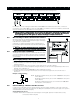
How to Program S E C T I O N 4 The following section of the manual describes how to enter Installer Programming and how to program the various sections. It is extr emely impor tant that you rread ead the following section of the manual to completely understand how to extremely important pr ogram the panel. program 4.1 How to Enter Installer Programming Installer Programming is used to program all communicator and panel options.
H O W T O P R O G R A M Example: for the three digit account number ‘403’, you would enter [4], [✱] [1] [✱] [3], [0]. [4] to enter the digit 4 [✱] to enter Hexadecimal mode (Ready light flashes) [1] to enter A [✱] to return to decimal mode (Ready light is solid) [3] to enter the digit 3 [0] to enter the digit 0 as a filler digit. 4.4 Programming Toggle Option Sections Some Sections contain several toggle options.
Program Descriptions S E C T I O N 5 The following section explains all the programmable features including how the feature operates, options that pertain to the feature and a summary of program locations that require programming. 5.1 Zone Definitions These sections will allow you to select how each of the 32 zones will operate. Each zone requires a 2 digit entry. In addition to selecting how each zone will operate, attributes may be pr ogrammed by zone (See programmed Section 5.
P R O G R A M D E S C R I P T I O N S [09] 24 Hour Supervisory Zone If this zone is violated, whether armed or disarmed, the panel will report to the central station, and log the zone fault. This zone gives a silent alarm by default. Do not wir e 24-Hour Super visor y zones on keypad zone ter minals. wire Supervisor visory terminals.
P R O G R A M D E S C R I P T I O N S Force Arm Enable Determines if the system can be armed with the zone violated. At the end of exit delay, if this type of zone is violated, it will be ignored by the panel. Once the zone is secured it will be added back into the system. This zone attribute is useful for a garage door. The customer can arm the system with the garage door open. Later when the customer closes the door it becomes part of the system.
P R O G R A M D E S C R I P T I O N S ○ ○ ○ ○ ○ ○ ○ ○ ○ ○ ○ ○ ○ ○ ○ ○ ○ ○ ○ ○ ○ ○ ○ ○ ○ ○ ○ ○ ○ ○ ○ ○ ○ ○ 1st Phone Number .................................................. 2nd Phone Number ................................................. 3rd Phone Number ................................................. 3rd Phone Number Enable ..................................... Alternate Dial ..........................................................
P R O G R A M D E S C R I P T I O N S Please refer to Appendix A: “Reporting Codes”for a list of Contact ID Identifiers. ○ ○ ○ ○ ○ ○ ○ ○ ○ ○ ○ ○ ○ ○ ○ ○ ○ ○ ○ ○ ○ ○ ○ ○ ○ ○ ○ Contact ID Uses Programmed/Automatic Codes .. [381]: [7] ○ ○ ○ ○ ○ ○ ○ ○ ○ ○ ○ ○ ○ ○ ○ ○ ○ ○ ○ ○ ○ ○ ○ ○ ○ ○ ○ 5.6.3 SIA (Level 2) SIA is a specialized format that will communicate information quickly using frequency shift keying (FSK) rather than pulses.
P 5.7 R O G R A M D E S C R I P T I O N S Communicator – Reporting Codes Reporting codes must be programmed in order for the panel to report events to the central station. Reporting codes are two digits and can use hexidecimal digits A through F. To disable a reporting code, program it as “FF” (default setting) or “00”. All reporting codes are listed and described in Appendix A “Reporting Codes.” 5.7.
P R O G R A M D E S C R I P T I O N S on the Bell Output of the main panel. The Bell Circuit Trouble Restoral Reporting Code will be transmitted as soon as the problem is corrected. A Fire Trouble Alarm Reporting Code will be transmitted immediately when an open condition is measured on any Fire type zone (See Section 5.1 “Zone Definitions”). The Fire Trouble Restoral Reporting Code will be transmitted as soon as the problem is corrected.
P R O G R A M D E S C R I P T I O N S The time to complete a successful download can be significantly reduced with the use of the PC-Link. This adaptor makes it possible to perform on-site downloading. To Initiate Local Downloading via the PC-Link, enter [✱] [8] [Installer’s Code] [499] [Installer’s Code] [499]. All keypads will be busy for the duration of the PC-Link connection. The status LEDs will display the current system status on the keypad where the PC-Link was initiated.
P R O G R A M D E S C R I P T I O N S Please refer to the Control Panel Wiring Diagram in this manual for wiring instructions. Only ONE of options [03] Sensor Reset, [04] 2-W ir e Smoke and [20] [✱] [7] [2] Command Output 2-Wir ire Option #2 may be pr ogrammed on the same system. programmed [04] 2-Wire Smoke Support (PGM2 Only) PGM2 may be used in conjunction with two-wire smoke detectors.
P R O G R A M D E S C R I P T I O N S [15] Remote Operation (DLS-3 Support) This output can be activated and deactivated remotely using DLS software. [16] LINKS1000 Support (PGM1 Only) The output will be used as a data wire to communicate phone number information for the LINKS1000 cellular unit. [17] Away Armed The output will activate when the system is armed with the Stay/Away zones activated.
P R O G R A M D E S C R I P T I O N S ○ ○ ○ ○ ○ ○ ○ ○ ○ ○ ○ ○ ○ ○ ○ ○ ○ ○ ○ ○ ○ ○ ○ ○ ○ ○ ○ ○ ○ ○ ○ ○ PGM Output Attributes ............................................ PC5208 Attributes .................................................. PC5204 Attributes .................................................. PGM Output timer ...................................................
P R O G R A M D E S C R I P T I O N S ○ ○ ○ ○ ○ ○ ○ ○ ○ ○ ○ ○ ○ ○ ○ ○ ○ ○ ○ ○ ○ ○ ○ ○ ○ ○ ○ ○ ○ Test Transmission Reporting Codes ...................... Section [352] Test Transmission Time of Day .............................. Section [371] Test Transmission Cycles ....................................... Section [370] ○ ○ ○ ○ ○ ○ ○ ○ ○ ○ ○ ○ ○ ○ ○ ○ ○ ○ ○ ○ ○ ○ ○ ○ ○ ○ ○ ○ ○ 5.14 Fire, Auxiliary, Panic Keys The emergency keys are available on all keypads.
P R O G R A M D E S C R I P T I O N S exists. (See Section 5.17 “Swinger Shutdown”.) The event buffer can be viewed three different ways. It can be viewed through an LCD keypad, printed on-site using the PC5400 printer module (See Section 5.29 “On-Site Printer”) or it can be uploaded through the DLS software. 5.16.
P R O G R A M D E S C R I P T I O N S ○ ○ ○ ○ ○ ○ ○ ○ ○ ○ ○ ○ ○ ○ ○ ○ ○ ○ ○ ○ ○ ○ ○ ○ ○ ○ ○ ○ ○ ○ ○ ○ ○ ○ Arm/Disarm Bell Squawk ........................................ Bypass Status Displayed While Armed ................. WLS Key Uses Access Codes ............................... Opening After Alarm Keypad Ringback ................. Opening After Alarm Bell Ringback ....................... Closing Confirmation ..............................................
P 5.23 R O G R A M D E S C R I P T I O N S Keypad Blanking If the Keypad Blanking Option is enabled the panel will turn off all lights and LCDs on the keypads if no key is pressed for 30 seconds. The keys, however, will remain backlit. The panel will turn the lights and LCDs back on if entry delay begins or an audible alarm occurs. The lights and LCDs will also come on if a key is pressed or, if the Code Required to Restore Blanking Option is enabled, a valid access code is entered.
P 5.26.4 R O G R A M D E S C R I P T I O N S LINKS Special Preamble In some areas of North America, dialing #DAT or ✱DATA reduces the cellular billing increment. The LINKS Special Preamble (section [393]), allows the use of [✱] and [#] characters for the programming of #DAT and ✱DATA. The LINKS Special Preamble is sent BEFORE the Preamble programmed in Sections [390] to [392].
P 5.28.2 R O G R A M D E S C R I P T I O N S Factory Default Main Panel (Software) and other Modules Step 1 - Enter Installer Programming. Step 2 - Enter Program Section [99X]. Step 3 - Enter the Installer Code. Step 4 - Enter Program Section [99X] again. The panel will take a few seconds to reset. When the keypad is operational, the default is complete.
Reporting Codes A P P E N D I X V A Contact ID SIA Format (Level 2—Hardcoded) The first digit (in parentheses) will automatically be sent by the control. The last two digits are programmed to indicate specific information about the signal. For example, if zone 1 is an entry/exit point, the alarm reporting code could be programmed as [34]. The central station would receive the following: *BURG - ENTRY/EXIT - 1 In the above example, the “1” indicates which zone went into alarm.
R Section # E P O Reporting Code [344-348] Openings R T I N G V Code Sent When... system disarmed (user 01-34, 40-42 indicated) C O D E S Dialer Direction* Automatic Contact ID SIA Auto Rep Codes** O/C (4) A2 OP-UU [348] Auto Arm Cancellation auto arm cancelled O/C (4) A5 CE-00 [348] Special Opening O/C (4) AA OP-00 Opening (disarming) using one of the following methods: keyswitch, maintenance code, DLS software, wireless key [349-350] Battery Trouble/Rest.
Zone Reporting Codes A P P E Table B-1 Zone Alarm/Restoral Reporting Codes For notes on Contact ID or SIA formats, see Appendix A. Zone Definition SIA Auto Rep Codes** Delay, Instant, Interior, Delay Stay/Away, Interior Stay/Away, 24-hr Burg.
PC5015 Control Panel Wiring Diagram A P P E N D 42 I X V C
Modules Supported on the PC5015 v2.2 A Module P P Supported Escort5580 Yes PC5204 Yes PC5208 Yes E N D I X V D Comments PC5108 Yes PC5108L Yes PC5132 v1.X Yes No support for Wireless Keys, Pendants or Handheld Keypads PC5132 v2.X Yes No identified Wireless Keys support PC5132 v3.X Yes PC5506 No PC5508 Yes PC5508Z Yes PC5516 Yes PC5516Z Yes PC5532 Yes PC5532Z Yes LCD5500 v1.X Yes LCD5500Z v2.X Yes PC5908 No PC5928 Yes PC5400 v1.X to v2.1 Yes PC5400 v2.
FCC COMPLIANCE STATEMENT CAUTION: Changes or modifications not expressly approved by Digital Security Controls Ltd. could void your authority to use this equipment. This equipment has been tested and found to comply with the limits for a Class B digital device, pursuant to Part 15 of the FCC Rules. These limits are designed to provide reasonable protection against harmful interference in a residential installation.
©2002 Digital Security Controls Ltd. Toronto, Canada • www.dsc.com Technical Support: 1-800-387-3630 Printed in Canada 29003272 R005 Direct all comments and suggestions concerning DSC publications to pubs@dscltd.