System Introduction S 1.
S Y S T E M I N T R False Alarm Prevention Features • Audible Exit Delay • Audible Exit Fault • Quick Exit • Swinger Shutdown • Communication Delay O D U C T I O N • Urgency on Entry Delay • Recent Closing Transmission Additional Features • Auto Arm by Partition at Specified Time • Keypad Activated Alarm Output and Communicator Test • Keypad Lockout • Audio Capability using the PC5928 Audio Interface Module which allows local intercom and Central Station 2-Way Listen in.
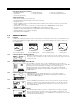
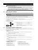
S Y S T E M I Three addtional devices are available: PC5921 1.2.7 PC5921EXT PC5921EXT/R N T R O D U C T I O N PC5921 Intercom Audio Station The PC5921 Intercom Audio Station can be used in conjunction with the PC5928 Audio Interface Module. PC5921 EXT Door Box Audio Station The PC5921 EXT Door Box Audio Station can be used in conjunction with the PC5928 Audio Interface Module.
Getting Started S E C T I O N 2 The following sections provide a complete description of how to wire and configure devices and zones. 2.1 Installation Steps The following steps are provided to assist with the installation of the panel. It is suggested that you read over this section briefly to get an overall understanding of the order of installation. Once this is done carefully work through each step.
G E T T I N G S T A R T E D Note: In order to comply with safety requirement IEC950, ensure that when the mains cabling enters the alarm panel, it is securely clamped to prevent it from being removed. The panel requires a 16.5 volt, 40 VA transformer. Connect the transformer to an unswitched AC source and connect the transformer to these terminals. Do not connect the transformer until all other wiring is complete.
G E T T I N G S T A R T E D Ensure the plugs and jacks meet the dimension, tolerance and metallic plating requirements of 47 C.F.R. Part 68, SubPart F. For proper operation there must be no other telephone equipment connected between the control panel and the telephone company facilities. Do not connect the alarm panel communicator to telephone lines intended for use with a FAX machine.
G E T T I N G S T A R T E D Other Devices Read the manufacturer’s literature carefully to determine the maximum current requirement (during activation or alarm) and use this value for loading calculations. Do not allow connected devices to exceed the system capabilities during any possible operational mode. 2.5 Assigning Zones to Zone Expanders The main panel contains zones 1 to 8. Additional zone expanders may be added to increase the number of zones on the system.
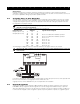
G 2.6.1 E T T I N G S T A R T E D How to Assign Keypads All keypad assignment must be done individually on each keypad on the system. To assign a keypad to a slot and select the partition it will operate, enter the following: Step 1 — Enter Installer Programming Step 2 — Press [000] for Keypad Programming Step 3 — Press [0] for Partition and Slot Assignment Enter a two digit number to specify the partition and slot assignment.
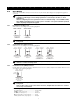
G 2.9 E T T I N G S T A R T E D Zone Wiring There are several different ways in which zones may be wired, depending on the programming options selected. Any zone defined as a Fire zone will automatically require a single End of Line (EOL) resistor regardless of which type of zone wiring supervision is selected (See Section 5.1 “Zone Definitions”).
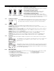
G 2.9.4 E T T I N G S T A R T E Fire Zone Wiring - 4 wire Smoke Detectors All zones defined as Fire (See Section 5.1 “Zone Definitions”) must be wired according to the following diagram: Do not use double EOL resistors for Fire zones. For a complete description of how fire zones operate, see Section 5.1 “Zone Definitions”. 2.9.
Keypad Commands S E C T I O N 3 All keypads provide complete information and control of the alarm panel. The panel can be completely programmed via any keypad on the system. LED keypads provide function indicator lights and individual zone indicator lights for the alarm circuits. The LCD keypad provides function indicator lights and word descriptions for zone status. The following sections describe how to arm, disarm and perform other keypad functions. 3.
K E Y P A D C O M M A N D S To disarm the panel enter the premises through the designated entry/exit door. The keypad will emit a steady beep to warn that you must disarm the system. During the last 10 seconds of entry delay the panel will pulse the keypad beeper on and off rapidly to warn the entry delay is about to expire. Enter a valid Access Code at the keypad. If an error is made press the [#] key and enter the code again.
K [ ]+[2] E Y P A D C O M M A N D S Trouble Display The panel constantly monitors itself for several different trouble conditions. If a trouble condition is present the ‘Trouble’ light will be on steady and all keypads will beep twice every 10 seconds. The trouble beep can be silenced by pressing any key on any keypad. To view trouble conditions: 1. Press [ ] [2]. 2. The keypad will flash the ‘Trouble’ light and light zones to indicate which trouble conditions are present.
K [ ]+[3] E Y P A D C O M M A N D S Alarm Memory The ‘Memory’ light will be on if any alarm occurred during the last armed period or if an alarm occurred while the panel was disarmed (24 hour zones). To view alarm memory: 1. Press [ ] [3]. 2. The keypad will flash the Memory light and light up zone lights to indicate alarm or tamper conditions that occurred during or since the last armed period. When the panel is armed the ‘Memory’ light will go out.
K E Y P A D C O M M A N D S How to program Access Code Attributes: “Master Code” attributes cannot change. By default, each code has the attributes of the code used to program it. 1. Enter [ ][5][Master Code]. The keypad will flash the ‘Program’ light and turn on the zone light for any code already programmed. 2. Press [9] to enter the Attribute mode. The keypad will turn on the ‘Ready’ light and turn off the armed light. 3.
K E Y P A D C O M M A N D S • [7] - Enable Background Music If the intercom is being used to provide background music, press the [7] key to toggle the background music feature on and off. Additional Features are available using on the LCD keypad. These features do not have numbers assigned. Use the arrow keys (< >) to scroll through the [ ] [6] menu and press the [ ] key to select the following commands.
K 3.5 E Y P A D C O M M A N D S Function Keys There are 5 function keys on the PC5016 keypads labelled Stay, Away, Chime, Reset and Exit. The operation of these keys is described below. The function is activated by pressing and holding the key for 2 seconds. “Stay” - Stay Arm Arms the partition to which the keypad is assigned. All Stay/Away type zones will be automatically bypassed. Delay type zones will provide entry and exit delay.
K E Y P A D C O M M A N D S [08] - [ ]+[1] Bypass Mode This function key provides the user with a simple method for entering the Bypass Mode. If a user code is required it must be entered before bypassing can be performed (See Section 3.4 “[ ] Commands, [ ] [1] Zone Bypass”). [09] - [ ]+[2] Trouble Display This function key provides the user with a simple method for entering the Trouble Display Mode (See Section 3.4 “[ ] Commands, [ ]+[2] Trouble display”).
How to Program S E C T I O N 4 The following section of the manual describes how to enter Installer Programming and how to program the various sections. It is extremely important that you read the following section of the manual to completely understand how to program the panel. 4.1 How to Enter Installer Programming Installer Programming is used to program all communicator and panel options. The Installer Code is [5016] at default but may be changed to prevent unauthorized access to programming.
H O W T O P R O G R A M If you enter information into a section and make a mistake, press the [#] key to exit the section. Select that section again and re-enter the information correctly. If you are using a pulse format, a decimal zero [0] does not transmit. Programming a zero [0] tells the panel not to send any pulses for that digit. Decimal zero [0] is a filler digit. To make a zero [0] transmit, it must be programmed as a Hexadecimal ‘A’.
Program Descriptions S E C T I O N 5 The following section explains all the programmable features including how the feature operates, options that pertain to the feature and a summary of program locations that require programming. 5.1 Zone Definitions These sections will allow you to select how each of the 32 zones will operate. Each zone requires a 2 digit entry. In addition to selecting how each zone will operate, attributes may be programmed by zone (See Section 5.2 “Zone Attributes”).
P R O G R A M D E S C R I P T I O N S [08] Standard 24 Hour Fire Zone When violated the panel will immediately latch the alarm output and communicate to central station. The alarm will sound for the Bell Cutoff time programmed in Section [005], “System Times” or can be programmed to sound until a valid code is entered, Section [014], “Second System Option Code, option [8]”. If a Fire zone is violated it will be displayed on all keypads. Typically this zone is used for pull stations.
P R O G R A M D E S C R I P T I O N S ○ ○ ○ ○ ○ ○ ○ ○ ○ ○ ○ ○ ○ ○ ○ ○ ○ ○ ○ ○ ○ ○ ○ ○ ○ ○ ○ ○ ○ ○ ○ ○ ○ ○ ○ ○ ○ ○ ○ Zones 1 to 32 Attributes ................................ Section [101] - [132] Audible/Silent Alarm ...................................... Section [101] - [132], Option [1] Pulsed/Steady Alarm ..................................... Section [101] - [132], Option [2] Activate Chime ...............................................
P 5.5 R O G R A M D E S C R I P T I O N S Communicator - Account Numbers There are two Partition Identifier Codes (or Account Numbers) programmable, one for each Partition. The Account Number is used by central station to determine which panel is calling. If the panel is programmed as two Partitions both Account Numbers must be programmed. The panel will report to the central station by Partition.
P 5.6.3 R O G R A M D E S C R I P T I O N S SIA (Level 2) SIA is a specialized format that will communicate information quickly using frequency shift keying (FSK) rather than pulses. The SIA format will automatically generate the type of signal being transmitted, such as Burglary, Fire, Panic etc. The two digit reporting code is used to identify the zone or user code number.
P 5.7 R O G R A M D E S C R I P T I O N S Communicator - Reporting Codes The panel can be programmed to report events to a central station. The panel will send the reporting code programmed for the event. Reporting codes can be one or two digits and can use HEX digits (A through F). The following is a description of the different reporting codes that can be programmed and when the events will be reported to central station. 5.7.
P R O G R A M D E S C R I P T I O N S 5.7.6 Priority/Emergency The panel will transmit a Keypad Fire Alarm Reporting Code AND the Keypad Fire Restoral Reporting Code when the Fire Keys on any keypad is pressed for two seconds. The panel will transmit a Keypad Auxiliary Alarm Reporting Code AND the Keypad Auxiliary Restoral Reporting Code when the Auxiliary Keys on any keypad is pressed for two seconds.
P 5.8 R O G R A M D E S C R I P T I O N S Downloading Downloading allows programming of the entire control panel via a computer, modem and telephone line. All functions and features, changes and status, such as trouble conditions and open zones can be viewed or programmed by downloading. When power is applied to the panel downloading will be enabled for 6 hours. This will allow you to perform downloading without having to do any keypad programming.
P 5.10 R O G R A M D E S C R I P T I O N S PGM Outputs There are 3 different types of Programmable Outputs available. They are listed as follows: • PGM1 and PGM2 on the main board • 8 low current outputs available with the PC5208 Output Module • 4 high current outputs available with the PC5204 Power Supply/Output Module Programming any of the PGM Outputs is a two step process. First an option from the below list must be selected for the PGM Output.
P R O G R A M D E S C R I P T I O N S [10] Latched System Event The PGM output will activate when any of the selected events occur. It will deactivate when an access code is entered. Global alarms must be silenced with a global code. The normal PGM attributes, programmed in Sections [141] to [154] is replaced with the following list for any output selected as Latched System Event: Light [1] Burglary ......... Delay, Instant, Interior, Stay/Away and 24 Hour Burglary Zones Light [2] Fire ..
P R O G R A M D E S C R I P T I O N S When the trouble condition is restored the panel can send a TLM Restoral Reporting Code. Any events that occurred while the phone line was down will also be communicated. ○ ○ ○ ○ ○ ○ ○ ○ ○ ○ ○ ○ ○ ○ ○ ○ ○ ○ ○ ○ ○ ○ ○ ○ ○ ○ ○ ○ ○ ○ ○ ○ ○ ○ ○ ○ TLM Enable/Disable ...................................... Section [015], Option [7] TLM Trouble Only or Audible When Armed ... Section [015], Option [8] TLM Trouble Delay ........................................
P 5.15 R O G R A M D E S C R I P T I O N S Entry/Exit Delay Options Upon arming, the panel will begin the exit delay. If Audible Exit Delay is enabled the keypad will beep every second until the exit delay expires. The keypad will beep rapidly for the last 10 seconds of exit delay to warn the user the system is about to arm. For commercial applications Bell Squawk on Exit Delay may be enabled.
P 5.17 R O G R A M D E S C R I P T I O N S Swinger Shutdown The swinger shutdown feature is designed to prevent a runaway communicator from tying up the central station. Different limits can be programmed for Zone Alarms, Zone Tampers and Maintenance signals. After the panel has communicated the programmed number of transmissions for an event it will no longer report that event until the swinger shutdown is reset. For example, the swinger shutdown limit for Zone Alarms is set to [003].
P R O G R A M D E S C R I P T I O N S If no code is entered the panel will Auto-Arm. If a zone is violated the panel will transmit a Partial Closing Reporting Code if programmed to indicate the system was not secure. If the zone is restored the panel will add the zone back into the system. If the No Activity Arm option for a partition is programmed with a number other than 000, the partition will Auto-Arm if no activity is detected for the programmed number of minutes.
P R O G R A M D E S C R I P T I O N S ○ ○ ○ ○ ○ ○ ○ ○ ○ ○ ○ ○ ○ ○ ○ ○ ○ ○ ○ ○ ○ ○ ○ ○ ○ ○ ○ ○ ○ ○ ○ ○ ○ ○ ○ ○ ○ ○ ○ Keypad Tamper Enable ............................................. Section [016], Option [8] General System Tamper Reporting Code ................. Section [338] General System Tamper Restoral Reporting Code ... Section [338] ○ ○ ○ ○ ○ ○ ○ ○ ○ ○ ○ ○ ○ ○ ○ ○ ○ ○ ○ ○ ○ ○ ○ ○ ○ ○ ○ ○ ○ ○ ○ ○ ○ ○ ○ ○ ○ ○ ○ 5.
P 5.29.2 R O G R A M D E S C R I P T I O N S Factory Default Main Panel (Software) and other Modules Step 1 - Enter the Installer Programming mode. Step 2 - Enter Program Section [XXX]. Step 3 - Enter the Installer Code. Step 4 - Enter Program Section [XXX] again. The panel will take a few seconds to perform the default. When the keypad is again operational the default is complete.
P R O G R A M D E S C R I P T I O N S 3. AC/DC Inhibit Arming Enabled: When this option is enabled and there is an AC or DC trouble present on the system, the Ready Light will be OFF and the system will not be able to be armed. This includes Keypad, Keyswitch, Automatic and Downloading Arming. Arming will not be allowed until the AC or battery trouble is cleared.
Appendix A C O N T A C T I D Contact ID The Partition ID Codes must be 4 digits. All reporting codes must be 2 digits. The following is a list of Contact ID reporting codes. The first digit (in parentheses) will automatically be sent by the control. The last two digits are programmed to indicate specific information about the signal. For example, if zone 1 is an entry/exit point, the alarm reporting code could be programmed as [34].
Appendix B S I A V F O R M A T SIA Format Level 2 (Hardcoded) The SIA communication format used in this product follows the level 2 specifications of the SIA Digital Communication Standard - February 1993. This format will send the Account Code along with its data transmission.
Hookup Diagram P C 5 0 1 6 C O N T R O L P A N E L 40
LIMITED WARRANTY Digital Security Controls Ltd. warrants the original purchaser that for a period of twelve months from the date of purchase, the product shall be free of defects in materials and workmanship under normal use. During the warranty period, Digital Security Controls Ltd. shall, at its option, repair or replace any defective product upon return of the product to its factory, at no charge for labour and materials.
© 1997 Digital Security Controls Ltd. 1645 Flint Road, Downsview, Ontario, Canada M3J 2J6 Tel.
Installation Manual PC5O16 Version 1.1 WARNING This manual contains information on limitations regarding product use and function and information on the limitations as to liability of the manufacturer. The entire manual should be carefully read.
Table of Contents Section 1 – System Introduction Section 5 – Programming Descriptions 1.1 1.2 5.1 5.2 5.3 5.4 5.5 5.6 1.3 Specifications ...................................................................... 1 Additional Devices .............................................................. 2 1.2.1 Keypads .................................................................... 2 1.2.2 PC5108 Eight Zone Expander Module ..................... 2 1.2.3 PC5204 Power Supply Output Module .....................