
User manual


PWR-DSP1 User Manual
Page 11 of 23
Copyrights DSP4YOU ltd
3.3 Connectivity
3.3.1 Network
PWR-DSP1 requires at least one Ethernet connection for initial configuration of the DSP and AVB audio streaming. If
AVB is unused, unit do not require an Ethernet connection once configured. A standard-straight through Ethernet
CAT5/6 network is required for connectivity through a network switch. If your computer does not support auto-
switching, use a crossover CAT-5/6 cable instead.
PWR-DSP1 units utilize “Zeroconf” technology for Plug & Play integration.
- If a DHCP server is present at boot up, the PWR-DSP1 will automatically acquire an IP address from DHCP
- If no DHCP server is present at boot up, the PWR-DSP1 will use the Link Local Address (Auto IP) P 169.254.0.xxx
Note that no IP address needs to be remembered since units are discovered / remembered by their names in the
software.
Network requirements:
• Audio Video Bridging systems requires special AVB enabled network switches (so called AVB bridge) to
enjoy the advanced features of AVB such as the Stream Reservation Protocol (SRP). Such AVB bridge will
have the capability to shape the traffic of the network such that any AVB traffic has higher priority.
• Since AVB bridges are not readily available, the current configuration allows use of the PWR-DSP1 over a
standard 100/Gigabit network switches without any issue. To insure audio streaming without audio dropouts,
we recommend that you install PWR-DSP1 on a dedicated Ethernet network (at least 100Mbit) to be safe.
On Gigabit Ethernet networks with low traffic (bandwidth subscription), it’s possible to share the network
with other network devices. If in doubt, don’t hesitate to contact our technical support team at
info@dsp4you.com
3.3.2 Analog audio connectivity
PWR-DSP1 can accept balanced/unbalanced audio inputs on two Neutrik XLR connectors. An analog link out of
channel one is available on the XLR male connector.
Audio connectivity pin out
Balanced connection Un-balanced audio
1 = > Cable Shield
2 = > Positive cable
3 = > Return cable
1 = > Jumper link to -
2 = > Positive cable
3 = > Return cable (jumper to shield)
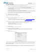
Template Connectivity Diagram
Windows PC
100Base T switch
PWR
-
DSP1
units
CAT5/6 cable
Wifi Access point
Laptop