
User manual


PWR-DSP1 User Manual
Page 6 of 23
Copyrights DSP4YOU ltd
2 Product Overview
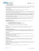
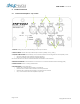
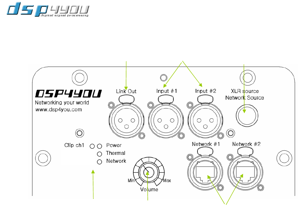
2.1 Front Panel Description – Top section
1. LINK OUT analog output for channel linking out from input channel 1.
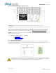
2. ANALOG INPUTS channel 1&2. Fully balanced input with Pin1 (shield), Pin2 (+), Pin3 (-)
3. XLR/AVB SOURCE SWITCH for momentary source selection between the analog and the network (AVB) source
o LED ON to indicate when module is using the XLR input
o LED OFF to indicate when module is using the AVB input
This source selection can also be controlled from the user interface of the software.
4. NETWORK CONNECTOR on Neutrik Ethercon connectors. For Control and Ethernet audio streaming (AVB)
5. MASTER VOLUME control on rotary potentiometer.
6. LED INDICATION for status indication:
o Power: ON to indicate when module is powered ON.
o Thermal: ON to indicate when module is in Thermal protection
o Network: ON to indicate when module is connected to the network
o Clip 1: ON to indicate when the amplifier output clips
1
2
4
5
6
6
3