Eurocom 612 Installation & Programming Manual
digital switch systems Eurocom 612 Small Office / Home Office Hybrid Telephone System CONFIDENTIALITY The information contained in this manual is the property of Digital Switch Systems Ltd. The contents of this manual must not be copied, distributed or made available to any third party without the prior written consent of Digital Switch Systems Ltd. "Every effort has been made to ensure that this manual documents the operation of the Eurocom 612 Telephone System.
Contents 1. System Overview 1 Introduction 1 General Description 1 System Capacity 2 2.
I n s t a l l a t i o n iv & P r o g r a m m i n g M a n u a l
Section 1 1. System Overview Introduction Purpose This manual provides the information needed to install, program and operate your telephone System, it should be used in conjunction with the market-specific specification sheet supplied with this manual. Regulatory Information Maintenance Limitations Maintenance on the Telephone System is to be performed only by authorised dealers and installers. The user is not authorised to make any changes and/or repairs except as specifically noted in this manual.
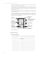
I n s t a l l a t i o n & P r o g r a m m i n g M a n u a l Detection, Call Logging, DISA, System Integral Call Answering, Remote programming and many others, Figure 1-1 shows many of the options available. The System supports approved single line telephones (DTMF or pulse), modems, facsimile and answering machines. In addition a Standard and Executive Terminal are available which provide extra features on the system.
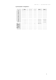
S e c t i o n 1 - S y s t e m O v e r v i e w System Expansion Configurations ISDN / Analogue hybrid system configurations Analogue only system configurations System Type Exchange lines + Extensions ISDN S0 bus Expansion slot 1 Expansion slot 2 (basic) 2 + 8 2 + 10 0+2 card 3 + 10 1+2 card 4 + 10 2+2 card 2 + 12 0+2 card 0+2 card 3 + 12 1+2 card 0+2 card 4 + 12 2+2 card 0+2 card 5 + 12 2+2 card 1+2 card 6 + 12 2+2 card 2+2 card 4 + 10 1 ISDN card 4
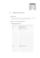
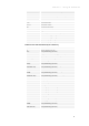
Section 2 2. Using an Extension Introduction Any standard tone telephone may be used with your telephone system. Extension programming and operations are carried out with a tone telephone plus a 100ms recall/flash key. Extension Codes Quick Reference Dialling and Feature Access Codes Access Code Dialled Service Feature Description 0 (or 9) Outgoing Exchange Line Call 1* ext.
S e c t i o n Access Code Dialled 2 – U s i n g a n E x t e n s i o n Service Feature Description * 21 ext. # Set All Call Diversion From Own Extension * 2 N ext. # Set Divert No Answer After delay N = 2 – 9 for 5, 10, … 45 sec. # 21 ext. # Cancel All Call Diversion from another extension # 21 # Cancel All Call Diversion from own extension # 20 # Cancel all diversions *31 ext. # Set Diversion On Busy #30 # Cancel Diversion On Busy #30 ext.
I n s t a l l a t i o n & P r o g r a m m i n g M a n u a l Feature codes on a Busy Call Access Code Dialled Service Feature Description 0 Exchange Line Call-back when free (Camp on) 1 Interrupt busy calls 2 Pick off TAM extension if connected to exchange line 3 Set exchange call to camp on extension 5 Extension call-back when free (Camp on) 6 Send message if calling party is busy (optional) 89 Exchange or extension call-back when free Key Descriptions to , & Number keypad.
S e c t i o n 2 – U s i n g a n E x t e n s i o n 1, 29 is reserved for door phone 2, while extension 10 is used to connect to the paging port. If you dial a code which is not valid, you will hear the error tone. As soon as you hear the error tone you may replace the receiver and then try again with the correct number. If the administrator has enabled call barring then external call may not be possible to all destinations.
I n s t a l l a t i o n & P r o g r a m m i n g M a n u a l Account Codes This feature is set up by the system administrator in order to keep a personal account of all external calls. It is not possible to make external calls without first entering '**' followed by your secret account PIN code. Enter account code PIN (now dial line and number) Go off hook and dial the code shown, followed by your account PIN number.
S e c t i o n 2 – U s i n g a n E x t e n s i o n Cancel all diversions Cancels all diversions. Cancel divert all and no answer Enter the cancel code, note this will not affect a divert on busy setting. Cancel divert on busy Enter the cancel code, note this will not affect divert on no answer. Cancel all call diversion from another extension ext. If the extension is receiving diverted calls from another extension then it is possible to cancel the setting from the receiving extension.
I n s t a l l a t i o n & P r o g r a m m i n g M a n u a l Add an external number The external number may be dialled after pressing Outside Lines’ section on page 7. numberÑ ÑanswerÒ Ò numberÑanswerÒ using any of the methods in the ‘Dialling Leaving a conference call Go on-hook. If the other calls were both external numbers they will be dropped, otherwise the callers are connected in a normal two-way call. Removing last caller from conference When on a conference call, press recall.
S e c t i o n 2 – U s i n g a n E x t e n s i o n Door Phones The Door phone is designed to work with this telephone system only. It provides a two-way speech link between any extension and the Door. The door phone has a call button for ‘ringing’ and a permanently lit LED for easy location. Extension numbers 19 and 29 are reserved for the Door Phones. Call Door Phone 1 Door phone 1 is connected automatically after a brief alert tone.
I n s t a l l a t i o n & P r o g r a m m i n g M a n u a l phone will be sent out to the exchange line. With a flash transparency call, it is not possible to use any features which require the use of key. the Calls should not be made for at least 3 seconds after replacing the handset on a call with flash transparency. Extension Call Back If the extension you are calling is busy, you may leave a call back indication, sometimes called camping on an extension.
S e c t i o n 2 – U s i n g a n E x t e n s i o n Put a call on exclusive hold While on a call press the recall button, you may then dial another number to make an enquiry call. If the extension hangs up the call will ring back your extension immediately. Ñon callÒ Ò Retrieve a call on exclusive hold Press recall. Ñon callÒ Ò Last Number Redial Redial last number Dials the last external number phoned from this extension. An external line will be seized automatically.
I n s t a l l a t i o n & P r o g r a m m i n g M a n u a l Page all terminals in an extension group group Dial 1*, follwwed by the extension group number 80 – 83. Page via public address system Dialling 10 will connect directly to the public address system, if connected. Reminder call It is possible to set an alarm which will ring at a set time of the day. It has a special ring sound shown in your country specific specification sheet, packaged with this manual.
S e c t i o n 2 – U s i n g a n E x t e n s i o n Ninety-nine system-wide speed dial numbers. These can be used by all extensions but only changed by the administrator. System speed dials are exempt from call barring. Ten personal speed dial numbers of up to 25 digits each, dialled with codes 70 – 79. These are unique to each extension and may be freely changed. Dial a speed dial number speed dial code Go off-hook and dial the speed dial code.
Section 3 3. System Programming Introduction All system programming is carried out from either extension 13 or a PC running the programming tool, connected via the V24 option card. In order to program from extension 13 a tone telephone must be used. The Executive Terminal simplifies the operation further by providing full menu driven programming on its built in display. The factory defaults on power-up prior to any programming are shown on page 67.
S e c t i o n 3 – S y s t e m P r o g r a m m i n g Special Programming Mode There is also a special programming mode that allows the installer to omit '*9' PIN prefixes when programming feature codes. To enter this mode at extension 13 dial the code above. You will hear confirmation tone followed by an interrupted dial tone. If you are using a Terminal at extension 13 the LED for extension 13 will stay on, indicating that the extension is busy.
I n s t a l l a t i o n & P r o g r a m m i n g M a n u a l Executive Terminal Extension programming menu Figure 3-1 shows the menus available for programming an extension from any Executive Terminal, note that the General Setting and ISDN setting menus are only available when connected to the master extesnion 13. Call diversion Data protection Do not disturb Send msg. Leave msg. on terminal Clear msg.
S e c t i o n 3 – S y s t e m P r o g r a m m i n g Executive Terminal System programming menu An Executive Terminal connected to extension 13 is able to enter a system programming mode with the code *9 PIN 9991 #. One further menu will then be made available for changing system parameters, shown in Figure 3-2. Set Exch 1 day mode Set Exch 2 day mode Set Exch 3 day mode Set Exch 4 day mode Set Exch 5 day mode Set Exch 6 day mode Set door ph.
I n s t a l l a t i o n & P r o g r a m m i n g M a n u a l System Programming Code Summary The prefix *9 is used to program a feature, *8 is used to activate it. The default PIN code is 7373. System programming can only be carried out at extension 13.
S e c t i o n Feature Boss – Secretary Mode (p 32) Call Barring (p 33) Call Detail Recording (p 35) Call waiting tone (p 37) Call Unit Cost (p 37) Courtesy Service (p 37) Day/Night Mode (p 38) – S y s t e m Programming Codes P r o g r a m m i n g Action *8 400 # Switch off automatic answering *8 531 # Enable boss – secretary working *8 530 # Disable boss – secretary working *9 PIN 981 F 1 number # Program number prefix to bar filter F *9 PIN 981 F 0 # Clear bar filter F *9 PIN 96 CFX
I n s t a l l a t i o n & P r o g r a m m i n g Feature Programming Codes Action *8 360 # Set day mode and disable automatic mode *8 361 # Set night mode and disable automatic mode *9 PIN 726 # Use switch on alarm loop 2 for day / night switching *9 PIN 361 EXT # Set extension as DTMF only. *9 PIN 360 EXT # Cancel extension as DTMF only.
S e c t i o n Feature 3 – S y s t e m Programming Codes P r o g r a m m i n g Action *9 PIN 0100 num # Program ISDN base number, card 1 *9 PIN 0102 num Program ISDN base number, card 1 incl. # (wait 5sec for conf. tone) *9 PIN 0100# Clear ISDN base number, card 1 *9 PIN 0200 num # Program ISDN base number, card 2 *9 PIN 0202 num Program ISDN base number, card 2 incl. # (wait 5sec for conf.
I n s t a l l a t i o n & P r o g r a m m i n g Feature System PIN Number M a n u a l Programming Codes Action *9 PIN 771 number # Program Confirmation Number (4 digits max) *9 PIN 71 type # Select Alarm loop 1 type *9 PIN 72 type # Select Alarm loop 2 type *9 PIN 7* type # Select Alarm loop type both loops type=1: internal, 2:ext no conf., 3: ext with conf., 4: int & ext no conf, 5: int & ext with conf.
S e c t i o n 3 – S y s t e m P r o g r a m m i n g Extensions which have account code operation set up but no valid account pin is entered will be assigned call barring class 4. This means incoming calls will be accepted but only emergency numbers and numbers found in the exempt table may be dialled. In order to dial other numbers the user must dial the account PIN code before the telephone number. System speed dial numbers are exempt from call bar checking after the account pin has been entered.
I n s t a l l a t i o n & P r o g r a m m i n g M a n u a l the day and is not to be confused with day/night programming. There is a separate code which acts as a 'master switch'. This is to enable and disable alternative carrier selection without losing any of the ACS programming.
S e c t i o n 3 – S y s t e m P r o g r a m m i n g Default No extension is set as an answering machine. Set TAM extension System Settings Miscellaneous PIN Set TAM Clear TAM extension System Settings Miscellaneous ext PIN Clear TAM Automatic Answering Automatic answering provides a powerful and simple way of giving callers access to extensions, external numbers, remote programming and the public address port without any user intervention.
I n s t a l l a t i o n & P r o g r a m m i n g M a n u a l Remote Programming Dial at auto answer. Remote programming allows the caller to change system settings remotely. All the codes listed in this manual may be entered at a remote location. defines the operation of remote programming. Figure 3-3 defines the operation of remote programming.
S e c t i o n 3 – S y s t e m P r o g r a m m i n g Remote Paging Dial at auto answer. It is possible to access the paging port from a remote location through auto-answer. The operation is defined in Figure 3-4.
I n s t a l l a t i o n & P r o g r a m m i n g M a n u a l DISA Dial at auto answer. The system can be set to answer incoming calls with a voice message, prompting the user to dial a specific extension, or dial ‘00’ to be diverted to an emergency external number. The external number is shared with the External call diversion feature, on page 40. Depending on the digits entered, the caller is put through to the correct extension directly, or to the emergency number.
S e c t i o n 3 – S y s t e m P r o g r a m m i n g Incoming Call Control Dial at auto answer. This prevents any extensions ringing until an access code is dialled. This is useful in situations where users are receiving unwanted calls and wish to limit access to a known group. When incoming call control is active on a line the normal 5.5-second timeout to become a general call does not apply. Incoming call control is accessed by dialling 5 at the answer tone, or after the end of the voice message.
I n s t a l l a t i o n & Key line = 0 for all exchange lines 1 - 6 for single exch. line ans_type = 1 for answer with tone 2 for answer with msg. 1 3 for answer with msg.
S e c t i o n 3 – S y s t e m P r o g r a m m i n g Call Barring The system has five call barring classes for each extension, a different barring class can be active for daytime operation and another for night time operation. The day/night switching details may be found on page 37. An extension may also be set up for account code operation. The call barring class is then dependant on the account number, not on the extension class of service, see page 24 for further details.
I n s t a l l a t i o n & P r o g r a m m i n g M a n u a l 4 5 6 7 8 9 The system has 9 user programmable barring filters and 9 user programmable exempt filters numbered 1 to 9 which can be switched in or out in each class.
S e c t i o n 3 – S y s t e m P r o g r a m m i n g It is recommended that the optional V24/PC Program be used to change call barring defaults or to program exempt or additional barred numbers. Users unfamiliar with the system should not attempt advanced programming. If you have run into problems and wish to restart programming, you can reset the Call barring programming to the default data that was originally provided. To reset to default data: *9 PIN 990 # 990 #.
I n s t a l l a t i o n & P r o g r a m m i n g M a n u a l Telephone numbers over 26 digits in length are truncated. If a call is transferred then the call is logged against the extension which originally made (or received) the call. The start time and duration of call are measured using the internal real time clock. Note: The start time is measured from dialling the last digit for outgoing calls and answering the call on incoming calls.
S e c t i o n 3 – S y s t e m P r o g r a m m i n g Switch CDR output to PC program format (ASCII CDR information plus binary PC program information) General Settings CDR Off Enable hotel call logging for an extension ext Disable hotel call logging for an extension (remember to clear the extension’s call log with code below) ext Send call details for hotel logging enabled extension to printer ext Mask last 4 digits of telephone number in CDR record Show full telephone number in CDR record Log
I n s t a l l a t i o n & P r o g r a m m i n g M a n u a l designated courtesy service extension for a further 30 seconds. If it is still unanswered after this time the caller will be disconnected. Note that this service will be overridden by any other auto-answer modes or external call diversion, if set up on the same exchange line. The day and night messages are shared between the auto-answer modes and courtesy service so they cannot both use voice messages.
S e c t i o n 3 – S y s t e m P r o g r a m m i n g Switch on automatic day/night switching General Settings Clock Settings Automatic mode Manual Day/Night Setting by programming code Set to Day Mode and switch off automatic day/night switching General Settings Day-Night mode Adhoc day mode Set to Night Mode and switch off automatic day/night switching General Settings Day-Night mode Adhoc night mode Manual Day/Night Setting with switch Use switch on alarm loop 2 for day/night switching System
I n s t a l l a t i o n & P r o g r a m m i n g M a n u a l Extension locking Each extension may be locked from accessing external lines by entering the lock code *7*#. It may be unlocked by dialling the code *7* PIN #, where PIN is a 3-digit code unique to each extension. The PIN numbers for each extension are programmed as follows: Default Each extension may use any 3-digit code to unlock an extension.
S e c t i o n 3 – S y s t e m P r o g r a m m i n g As only one fax detector is fitted it is recommended that fax detection is set up on one exchange line only. This will prevent problems where a fax on two simultaneous incoming calls may not be detected. There are two automatic fax-switching modes. Automatic answer mode This mode answers with a tone or voice message recorded by the user and looks for fax tone to determine if it is a fax call.
I n s t a l l a t i o n & P r o g r a m m i n g M a n u a l Hold and ring timers The system provides many programmable timers to change the duration of ringing and the time exchange line calls can be left on hold or unanswered. Key delay (x30s) = 1 – 9 for delay in multiples of 30 seconds, 1=30, … 9=4.5min delay (x15s) = 1 - 9 for delay in multiples of 15 seconds, 1=15, … 9=2m 15s. Exchange line hold timer.
S e c t i o n 3 – S y s t e m P r o g r a m m i n g It is not possible to assign an immediate hot line to extension 13 as to do so would block any further system programming. Default No hotlines are set.
I n s t a l l a t i o n & P r o g r a m m i n g M a n u a l CLIP data and CLIR status are sent to the ISDN network when an outgoing call is made. COLP data and COLR status are sent to the network when a call is answered. When an extension sets up or answers an external call the CLIP/COLP data is based on the MSN number programmed for the extension. If there is no MSN number programmed then the base number for that particular ISDN line is used.
S e c t i o n 3 – S y s t e m P r o g r a m m i n g Music on Hold When a caller is placed on hold they will hear one of two different sound sources. Default The caller will hear hold tone by default. Internal Hold tone - held calls will hear two brief tone bursts every 5 seconds. General Settings Music on Hold Internal Tone External music - held calls will hear the music source connected to MOH socket.
I n s t a l l a t i o n & P r o g r a m m i n g M a n u a l Extensions to ring for exchange lines and door phones Key line = 0 for all exchange lines r 1 - 6 for single exch.
S e c t i o n 3 – S y s t e m P r o g r a m m i n g maximum of 255 times until the alarm is correctly acknowledged. The flow diagram used for external alarm calls is shown in Figure 3-8 below. External alarm without notification is silenced by answering the external call. External alarm with notification is silenced and re-armed when the call is answered and the correct confirmation code is entered.
I n s t a l l a t i o n & P r o g r a m m i n g M a n u a l Default No alarms are enabled. All alarm external numbers are empty. All extensions are programmed to ring on internal alarm. Alarm loops sensors are set to normally closed, no entry delay. Programming It is recommended that inexperienced users use the PC program option for security alarm programming. Alarm programming codes should follow the seven steps in order below. This is to prevent incorrect setting of the alarm.
S e c t i o n Disarm the Alarm Loops System Settings 2 Alarms Disarm alarm 1 / PIN 3 – S y s t e m alarm_no P r o g r a m m i n g alarm_no Clear Alarm settings Alarm Master Reset (erases all settings) System Settings Alarms PIN Reset alarms Clear all Alarm 1 Settings (erases all settings) Clear all Alarm 2 Settings (erases all settings) PIN PIN System PIN Number The system PIN number is a security block to stop unauthorised access to system programming.
I n s t a l l a t i o n & P r o g r a m m i n g M a n u a l Voice Message Programming Note: a fax / voice option card is required for this service. Default There are no voice messages recorded by default. Key message = 1 for call diversion msg. 2 for auto-answer msg. 1 3 for auto-answer msg.2 4 for alarm call msg. 1 5 for alarm call msg. 2. 6 for alarm confirmation message 50 Voice Message Application Maximum Duration (sec.
Section 4 4. Installation Telephone System Installation The installer must visually check the Telephone System main equipment prior to actual power-up and making wiring connections to ensure correct programming and subsequent operation of the system. This check must include: An inspection of the main unit housing for damage during product delivery. An inspection of the fitted 220-240VAC Power Cord & Plug.
I n s t a l l a t i o n & P r o g r a m m i n g M a n u a l The Telephone System must not be subjected to harsh environmental conditions. To ensure easy servicing and reliable operation, several factors must be considered when planning the system installation. The following locations are to be avoided at installation sites: Avoid heat-producing or steam producing equipment. Avoid Areas with temperature and humidity extremes.
S e c t i o n 4 - I n s t a l l a t i o n Preliminary Procedures After the case has been wall mounted, connect one exchange line, and two extension telephones (11 and 12) Exchange Line 1 must be connected to EXCHANGE terminals marked CO1, line 2 to CO2, line 3 to CO3, line 4 to CO4, line 5 to CO5 and line 6 to CO6. Important! A DTMF telephone (or Executive Terminal) must be fitted to EXTENSION terminals marked ext.13. This is the Master Extension and is used for system programming.
I n s t a l l a t i o n & P r o g r a m m i n g M a n u a l Extension 14 is suitable for external wiring and is fitted with the required protection circuitry.
S e c t i o n 4 - I n s t a l l a t i o n Twisted pair wiring must be used to eliminate interference from other sources. Individual cable-runs between the extension device and the MDF Connection Terminals is a mandatory requirement (StarWiring technique). The maximum cable run lengths are as follows: Single Line Telephone Extensions (900Ω) 3285m Cable 0.4mm Executive / Standard Terminals / Door phone (mains power) 950 m Cable 0.
I n s t a l l a t i o n & P r o g r a m m i n g M a n u a l For System Terminals only Connect to the terminals marked ‘Ter 1’ or ‘Ter 2’. Extension connector block.
S e c t i o n 4 - I n s t a l l a t i o n If power is inadvertently left connected while installing or removing any expansion cards then before the telephone system is used it should be powered down. Whilst the cards will not be damaged the telephone system is designed to detect these cards during a self-test at power-up. Keep all PCBs in their protective anti-static bags until they are installed in the Main Unit. All PCBs that are not in protective bags should be handled by the card edges only.
I n s t a l l a t i o n & P r o g r a m m i n g M a n u a l For each SLT extension, the wiring pair must have a maximum DC loop resistance of 900Ω. Each system terminal maximum loop resistance is 200Ω under normal conditions (or 50Ω under battery back-up). Important! All extensions except extension 14 are for internal use only and are not suitable for external use without additional external lightning protection.
S e c t i o n 4 - I n s t a l l a t i o n 25Hz Ringer Card Note: This option may be fitted as standard, see Figure 4-6 on page 57 for the board location. Some older fax machines or automatic answering equipment may not be designed to operate with the 50Hz ringing generated by the telephone system. The ringer card option provides a true 25Hz sinewave ringing waveform to ensure compatibility. Important! 1. First disconnect the telephone system from the mains power outlet. 2.
I n s t a l l a t i o n & P r o g r a m m i n g M a n u a l ISDN Cards This optional card provides an interface to a basic rate ISDN exchange line. Support for 2 basic rate lines is possible with an ISDN card fitted into expansion slot 1 and expansion slot 2. Each ISDN card adds two exchange lines to the unit, using the two ISDN b channels on a basic rate ISDN connection. Two analogue extensions are also added with each ISDN card.
S e c t i o n 4 - I n s t a l l a t i o n The BBU is housed in a similar plastic case to the telephone system and is wall mounted. It is designed to operate with two 12V, 1.2 Ah sealed lead acid batteries of maximum dimensions 97 mm x 48.5mm x 57mm. The batteries are not supplied with the battery back up unit. This unit provides the telephone system with a 24 volt dc feed and a 75VRMS, 25Hz sine wave ringing supply.
I n s t a l l a t i o n & P r o g r a m m i n g M a n u a l 5. Remove the cover of the battery back up unit and proceed to install the batteries. Place the batteries on their side with the terminals facing the side of the case, as shown in Figure 4-8. 6. Using the short red cable with two spade connectors, connect the positive terminal (+) of the left-hand battery to the negative (-) terminal of the right hand battery. 7.
Section 5 5. Maintenance Self-Test The Telephone System initiates a 'self-test' when the 220-240VAC mains supply is switched on. This self-test power-on sequence includes: RAM Test PSTN Dial Tone Detection Expansion card detection Electronic Switching PSTN Exchange Line Ports PSTN Exchange Line Signalling Method (DTMF/Decadic) ISDN line status DTMF Resources The power-on self-test procedure takes about 10 seconds to complete.
I n s t a l l a t i o n & P r o g r a m m i n g M a n u a l Anti-static precautions should be taken before handling these boards as they could be damaged by electrostatic build up. Repair Procedures On site repair is limited to replacement of system option boards or the main board. The boards which maybe replaced by a trained and competent installation engineer are: Main 2+8 board 0+2, 1+2 & 2+2 expansion cards Fax / voice card V24 card ISDN card CLI detector card Meter Pulse detector card.
S e c t i o n 5 - M a i n t e n a n c e Outgoing calls do not get through Check that the line or host PABX extension is set for tone (DTMF) dialling if the extension you are using is DTMF. If the external line is pulse signalling then the extension must be pulse mode and vice versa. Check also that call barring class 5 (no outgoing calls allowed) is not assigned. Other ISDN equipment will not work with the telephone system Check the polarity of the connectors on the MDF to Figure 4-7 on page 60.
Section 6 6. Specifications For tone and ringing specifications please see the Country Specific Specification sheet packaged with this manual.
S e c t i o n Duration of DTMF Signal 65 ms. min. Inter-digit time 75 ms. min. 6 - S p e c i f i c a t i o n s Decadic Pulse Dialling Pulse Dialling rate 10 PPS Pulse Break/Make duration 66/33 Recall pulse 40 - 160ms for detect; 100ms for send PSTN CO Line Type Loop Calling, Unguarded clearing Power up default settings All extensions can make and receive external calls (call barring class 0) Alarm contacts are set to Normally Closed, 90-second entry delay, alarm with tone.
I n s t a l l a t i o n & P r o g r a m m i n g M a n u a l 7. Glossary 0+2 / 1+2 / 2+2 expansion cards COLP The 0+2 expansion card refers to a card which provides no exchanges lines and two extensions. Similarly the 1+2 and 2+2 cards provide 1 and 2 exchange lines respectively and 2 extensions. Connected line presentation. This shows the calling party your telephone number, if different from the dialled number. This is relevant in the case of MSN numbering.
G l o s s a r y KTS Recall Key telephone system. A system which uses it’s own system telephones, often with extra functions. This unit is a hybrid telephone system, capable of supporting both ordinary SLT and Terminal phones. See flash. MSN See Multiple subscriber number. RTC Real time clock. This is the clock inside the system which is backed up by battery and will not lose the time if power is lost and the BBU runs out of charge.
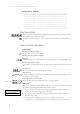
I n s t a l l a t i o n & P r o g r a m m i n g M a n u a l 8. Index 0+2, 1+2, 2+2 expansion cards.......... 57 CLIR .........................................44 accounts ................................... 25 using ..................................... 8 clock setting ...............................37 alarm calls .................. See reminder call connector locations ...................54 notification options ...................46 sensors ..................................46 social................
I n d e x executive-secretary ...See boss-secretary ISDN card............................... 60 location ................................ 51 MPD / CLI card ........................ 58 music source .......................... 60 terminals............................... 55 V24 card................................ 58 exempt filters............................. 34 internal alarm notification ..............46 expansion options.............................1, 2, 3 internal music on hold ...................
I n s t a l l a t i o n & P r o g r a m m i n g M a n u a l problem solving ........................... 64 programming code summary ..................... 20–24 how to ..................................16 introduction............................16 remotely................................28 special programming mode ..........17 system PIN number....................49 using executive terminal .............17 pulse dialling specifications............. 67 quick reference extension codes .....................
I n d e x 73
I n s t a l l a t i o n 74 & P r o g r a m m i n g M a n u a l
I n d e x 75
Digital Switch Systems Ltd. as manufacturer hereby declares that this product is in compliance with the essential requirements and other relevant provisions of the EC Directive 1999/5/EC. ©2002 Digital Switch Systems Ltd. Version 1.