DT595A USER MANUAL(EN) 2-Wire Video Intercom System Read this manual carefully before using the product, and keep it well for future use.
Parts and Function The door station is an audio door station without camera,which is designed for DT 2-wire system. The front panel is made of zinc alloy for better protection against vandalism & cauterization, and the call button is also made of zinc alloy with blue backlight for auxiliary illumination, the unlock and talking LED indicator guarantee the door station working efficiently. With the rainy cover, the door station can be strongly protection against water.
please refer to DT-CAM user instructions in details. PL(White): external lock power input, connect to the power positive(power +). S1+(Yellow): lock power(+) output. S1-(Black): lock power(-) output. Unit Mounting The location of outdoor station should keep away from snow,rain,and intensity light. Accessory contents: Accessories include a screwdriver T20, one M4X10 screw, two PA4X25 screws,three PA3x25 screws,three PM3x12 screws,and five screw stoppers Φ6X30.
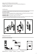
Multi Door Station Connection 4# Camera 3# Camera ID=11 2# Camera 1# Camera ID=10 ID=01 ID=00 ON ON ON ON 12 3 12 3 12 3 12 3 Monitors Bus PL S2+ S1+ S1- Bus PL S2+ S1+ S1- Bus PL S2+ S1+ S1- Bus PL S2+ S1+ S1- AC~ DIP=on,off,off A B C D DBC-4S PC6 OFF ON Impedance Switch BUS(Blue&Green); S2+(Red); PL(White); S1+(Yellow); S1-(Black); Multi Monitors Connection Basic IN-OUT wiring mode ON ON ON ON 1 2 3 4 5 6 1 2 3 4 5 6 1 2 3 4 5 6 1 2 3 4 5 6 Code=0, DIP-6=off Code=1, DIP-
With DBC-4S Wiring Mode ON monitor monitor 1 2 3 4 5 6 Impedance switch Code=14, DIP-6=on A B C D Code=15, DIP-6=on ON 1 2 3 4 5 6 Code=12, DIP-6=on Code=13, DIP-6=on ON 1 2 3 4 5 6 DIP=on,off,off monitor ON monitor Code=2, DIP-6=on Impedance switch A B C D Code=3, DIP-6=on monitor 1 2 3 4 5 6 1 2 3 4 5 6 Code=1, DIP-6=on DIP=on,off,off ON ON monitor OFF ON DBC-4S 1 2 3 4 5 6 ON monitor OFF ON DBC-4S ON 1 2 3 4 5 6 monitor 1 2 3 4 5 6 Code=0, DIP-6=on AC~ PC6 ID=00
With DT-CAM wiring mode The audio door station DT595A can be extended an additional CCTV camera to be a video door station. For more details about the camera, please refer to DT-CAM user instructions. DT-CAM AC~ ERL OUT IN PC6 DS DT595A Monitor IM Bus PL S2+ S1+ S1- Electric Lock Connection Door Lock Controlled with Internal Power 1 2 3 Connect one lock Note: 1. Electronic lock of Power-on-to-unlock type should be used. 2.
DIP Switch Setting The DIP switch is designed to set the code for door station and monitor, there are two states for each DIP switch, please refer to the following sketch map. ON(1) ON OFF(0) ON = = Door station DIP setting Total 3 bits can be configured, bit-1 and bit-2 are used to assign ID code for door station, bit-3 is used to match the video impedance.The switches can be modified either before or after installation.
Bit state ON 1 2 3 4 5 6 User code code=0 ON 1 2 3 4 5 6 ON 1 2 3 4 5 6 ON 1 2 3 4 5 6 ON ON 1 2 3 4 5 6 User code code=6 ON ON 1 2 3 4 5 6 Bit state code=1 code=2 code=3 code=4 1 2 3 4 5 6 ON 1 2 3 4 5 6 ON 1 2 3 4 5 6 ON 1 2 3 4 5 6 Bit state ON 1 2 3 4 5 6 User code code=11 ON code=7 code=8 code=9 code=10 1 2 3 4 5 6 ON 1 2 3 4 5 6 ON 1 2 3 4 5 6 ON 1 2 3 4 5 6 code=12 code=13 code=14 code=15 code=5 1 2 3 4 5 6 Specification • • • • • • Power Supply:DC 24V Power Consumptio
Cable Requirements The maximum distance of the wiring is limited in the DT system. Using different cables may also affect the maximum distance which the system can reach. The farest monitor monitor with two or four monitors monitor monitor DBC-4S B C AC~ PC6 When Monitor quantity < 20 Cable Usage A B C Twisted cable 2x0.75 mm2 60 60 30 80 80 40 A B C 70 30 20 70 50 30 Twisted cable 2x1 mm2 A When Monitor quantity >20 Cable Usage Twisted cable 2x1 mm2 Twisted cable 2x1.
The design and specifications can be changed without notice to the user. Right to interpret and copyright of this manual are preserved. DT-ENG-595A-V1 P120924 . Right to interpret and copyright of this manual are preserved. Printed 2012.
DT-DJ4S Audio Phone User Manual 8888 1 2 Read this manual carefully before using the product, and keep it well for future use.
1. Parts and Functions 97.1 33.
2. Operation Instructions 1) Door opening function: When visitor calls from outdoor station, the monitor rings, pick up handset to talk with the visitor, then press the Unlock button to open the door. If the system connect 2 locks,press Unlock 2nd button to open the second door. 2) Monitoring & calling menu: Pick up handset in standby mode,the LED will be shown a scroll information “Intr Call”,pressing Up button or Down button can stop the scroll. To quit this menu, please tap Cancel button.
Setting Item LED state Description Default Door bell call tone 3-xx Set the ring tone calling from door bell. Total 12 pieces ring tones can be selected(xx=01~12),press Up button or Down button to increase/decrease the value,settings will be performed immediately. 02 Ring volume 4-rx Set the ring volume for call tone,range from 0~9. 6 5-0x Maximum 4 door stations can be selected,this item is used to set the numbers of door station that can be surveilled by indoor monitor.