
User Manual

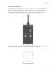
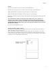
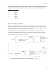
Table Of Contents

01/08/02
RCT-1 Switch Encoder and RCR-2 Switch Receiver Module
Detailed operating instructions, frequency and code options.
Encoder
The purpose of the RCT-1 Switch Encoder and RCR-2 Switch Receiver Module is to remotely activate
audio transmitters, recorders, camera, encryption, and microwave video transmitter packages via a secure
wireless link at distances up to 100 Meters. The handheld encoder is a license-free, Part-15 battery operated
device with an integral rubber duck antenna. The low power 900 MHz signal is digital FSK modulated and
digitally coded for security.
Switch Receiver
The miniature switch receiver unit, which detects this signal, is typically inserted between a power source
like a battery pack and a load. Voltages as high as 30 VDC at 2 Amps or 117 VAC at ½ Amp can be
switched.
The control signal from the RCT-1 is also digitally coded with an 8-bit user selectable address. Seven user-
selectable channels in the 902-928 MHz band are made available. This band was selected because it is
likely to be different from the frequencies used in the audio transmitter or microwave video link, thus
reducing the possibility of interference from these transmitters.
As configured from the factory, the switch receiver unit provides a dry switch closure. The small antenna
provided must be attached to the connector located on the module. Range extension can be accomplished
by locating the unit as high and in the clear as possible with the antenna in a vertical orientation. External
antennas such as standard 900 MHz GSM cellular vehicular antennas are also useful.
Security
The digital bitstream which includes the ON and OFF bits is encoded. 7 channels in the 902 –928 MHz
band are available and these are user –selectable via a rotary switch located on the PCB, by removing the
cover. The receiver must be pre-set to the same channel as the handheld encoder.
Channel Frequency
0 903.370
1 906.370
2 907.870
3 909.370
4 912.370
5 915.370
6 919.870
7 921.370
In addition to matching the channel setting, the 8 security address bits of the receiver must exactly match
that of the encoder. The security address bits are set via a dip switch on the PCBs.
Independent ON and OFF Commands
The control signal is of very short duration (< 5 seconds) and is intermittent in nature. That is, it only needs
to be sent once for turn on or turn off. Rather than a simple toggle state system, independent ON and OFF
commands are recognized. This eliminates the problem of not knowing or remembering what the last state
the receiver was in.
The command buttons (VIDEO ON and VIDEO OFF) should be pressed for a minimum of 2
seconds. ALWAYS TEST THE SYSTEM TO ASSURE THAT THE ENCODER AND SW
RECEIVER ARE SET PROPERLY AND FUNCTION BEFORE DEPLOYMENT.
1