
User Manual

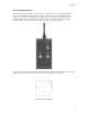
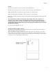
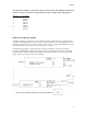
Table Of Contents

01/08/02
Note: When this transmitter is operated in countries outside the USA with a 900 MHz GSM network,
channels 5, 6 and 7 are preferred, since they fall between the TX and RX cellular band segments.
Channel Frequency
0 903.370
1 906.370
2 907.870
3 909.370
4 912.370
5 915.370
6 919.870
7 921.370
RCR-2 Switch Receiver Module
The RCR-2 (Remote Control Receiver) can be operated from 6 to 16 VDC and draws less than 20 mA in
all modes. It is equipped with an antenna, and two screw terminal blocks, one for external DC power and a
block for the normally open relay contacts. A small “noodle” antenna, equipped with an MMCX connector,
is provided with the receiver. The size of the unit is 5 X 1 X ½ Inches.
The hookup diagram shows a typical application; the RCR-2 controlling a 1 watt audio surveillance
transmitter, both SHARING a single power supply. The battery pack should be designed to support both
the ON time of the 1 Watt transmitter and the standby current of the switch receiver over the operational
period. Separate power sources may also be employed.
4