
User Manual

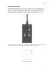
Table Of Contents
01/08/02
5
Latching Relay Feature
The Switch Receiver Module controls the power to the system via a latching type relay. This relay does not
require power to remain in the last state that it was set to. That is, if it was set to provide power and the
power source is removed, the relay remains latched.
Power On Reset
When the Switch Receiver Module is initially powered or is power is removed for 5 second or more and it
is reapplied (attaching a rechargeable battery for instance), the relay will automatically default to the OFF
or OPEN state.
Standby Operation / Operating Life
When the Switch Receiver Module is in the OFF state, only the receiver module is drawing current. This
drain is typically less than 20 mA. With a fully-charged 2 Ampere–Hour battery, the unit could remain in
standby for two days (48 Hours) and still provide more than 1 hour of video transmission.
Controlling Other Devices
The unit, as configured from the factory, provides a switched dry contact normally open set of contacts.
These contacts are closed when the ON command is received. Any external voltage up to 30 VDC at 2
Amps or 117 VAC up to 0.5 Amps can be controlled. Normally open (N.O.) contacts have been brought
out to the terminal block.
Changing Channels or Address Code bits
The RCR-2 channel switch and address switch may be accessed by first removing power and unscrewing
the four flathead Phillips screws holding the ABS case to the standoffs. The ABS housing will fall off
revealing the circuitry. The figure above shows the location of the channel and address switches. After
setting the switches, replace the cover and screws.
FCC Information:
DTC Communications, Inc.
75 Northeastern Blvd.
Nashua, NH 03062
Model RCT-1
FCC ID: H25 RCT1
This device complies with Part 15 of the FCC Rules.
Operation is subject to the following two conditions:
1. This device may not cause harmful interference.
2. This device must accept any interference including
interference that may cause undesired operation.