
User Manual

Op1920104 REV B 04/09/01 Page 3 of 7
TEMPORARILY SWITCH TO ANOTHER CHANNEL; IF THE TRANSMIT
CONDITION STOPS: YOU MAY BE RECEIVING ANOTHER TRANSMISSION
ON THE ORIGINAL CHANNEL.
When the repeater is used in some high noise environments, the squelch may need to be
tightened by turning the squelch control slightly CW until the repeater stops transmitting
(with no input signal). Test the squelch by turning the transmitter on and off a few times.
Remember that adjusting the squelch too far CW (tight) will reduce the range of the
repeater. If you can, try another transmitter channel, which is free of interference.
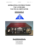
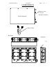
CONTROLS:
1. Channel Switches:
• RX- adjust the slot in the recessed switch labeled RX so that it aligns with the
proper receive channel.
• TX- adjust the slot in the recessed switch labeled TX so that it aligns with the
proper transmit channel.
2.
On–Off–Test Switch:
•
OFF POSITION- This is a maintained center position switch. In the center position all
power is removed from the Repeater Electronics.
• ON POSITION- This is a maintained position of the switch. To operate the
repeater move the switch to the upper position labeled ON this will apply power
to the repeater electronics.
• TEST- this is a momentary position and is used to verify that power is being
applied to the repeater and that the Transmitter is functional. Momentarily move
the switch to the position labeled test, hold the switch in this position. the TEST
LED should light indicating that power is connected to the repeater. In addition
the transmitter is turned on allowing the user to verify operation of the
transmitter.
3. Power Connector:
• Attach the cigarette plug end of the power cord to the vehicle's power socket
and the other end to the Tactical Repeater's power connector. When using the
optional battery pack a different cable is supplied. This cable connects the
battery pack to the Tactical Repeater
.
4. Antenna BNC Connector:
• Connect the supplied antenna to the BNC connector on the TAC-COM 2001
Tactical Repeater. This connection requires a 50-ohm antenna.
Do not turn the repeater on without an antenna attached.
Orient the external “rubber ducky” antenna so that it is in a vertical position. A higher
location like the top story of a building will almost always produce better results than a
below ground level location. Repeater installations near the outer wall or windowed part of
a building will produce better results than inner rooms. If the repeater is to be enclosed in
the trunk of a car, a remotely located, external antenna may be required for best