DIGITAL THEATER SYSTEMS, Inc. Digital Sound for Movies DTS-6 INSTALLATION AND OPERATION MANUAL 35mm P/N 9301E111002/01 February , 2001 DTS SA, England Telephone: 44-1189-349199 Fax: 44-1189-349198 Digital Theater Systems, Inc.
DTS-6 Installation Manual TABLE OF CONTENTS SECTION PAGE I. INTRODUCTION.............................................................................…........ 1-1 II. UNPACKING............................................................................................... 2-1 III. INSTALLATION PROCEDURE...................................................….......... 3-1 Timecode Reader Installation........................................................................ 3-1 DTS-6 Processor Installation..
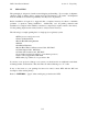
DTS-6 Installation Manual EMI NOTICE This equipment has been tested and found to comply with the limits for a Class A digital device, pursuant to Part 15 of the FCC Rules. These limits are designed to provide reasonable protection against harmful interference when the equipment is operated in a commercial environment.
DTS-6 Installation Manual WARRANTY INFORMATION Equipment manufactured by Digital Theater Systems, Inc. is warranted against defects in materials and workmanship for one year from date of purchase. There are no other express or implied warranties. Digital Theater Systems, Inc. obligation is restricted to repair and replacement of defective parts. Under no circumstances will Digital Theater Systems, Inc. be liable for any other damage, either direct or consequential.
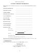
DTS-6 Installation Manual FACTORY WARRANTY INFORMATION The following is a list of information necessary for every location where the Digital Theater System is installed.
DTS-6 Installation Manual RACK-MOUNTED INSTALLATIONS If this product is installed in a closed or multi-unit rack assembly, the following items must be considered. 1. The ambient temperature within the rack may be greater than room ambient temperature. The maximum temperature for the equipment in this environment is 50°C. Consideration should be given to the maximum rated ambient. 2.
DTS-6 Installation Manual NOTES Thank you for choosing DTS ! vi
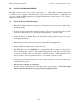
DTS-6 Installation Manual I. Section 1: Introduction INTRODUCTION The DTS digital sound process for motion pictures is designed for the digital sound release of motion pictures in 6-track theaters. It is a dual system in that the digital audio data is recorded on CD-ROM discs. A special DTS timecode is printed on the motion picture print along with a conventional stereo optical soundtrack. The timecode is used by the DTS system to synchronize the sound and picture.
DTS-6 Installation Manual II. Section 2: Unpacking UNPACKING The packaging is designed to handle normal shipping and handling. Upon receipt of shipment, check for signs of damage before opening and report all damage to the carrier. All shipments made from DTS are customer responsibility once they leave our premises. Before installation is begun it is suggested that a complete inventory be taken to minimize problems or questions during installation.
DTS-6 Installation Manual III. Section 3: Installation Procedure INSTALLATION PROCEDURE The DTS system consist of two major components: Q DTS Timecode Reader Head and R DTS-6 processor (player). The following is a generic procedure intended to supplement the processor installation wiring diagrams for specific manufacturer's sound systems. Look for these diagrams in Section VIII. 3.
DTS-6 Installation Manual 3.2 Section 3: Installation Procedure DTS-6 Processor Installation DTS has configured your DTS-6 processor to interface to the cinema processor as indicated on the packing list. A DTS-6 labeled “generic” will be set for stereo surrounds, subwooferdisable turned off, and platter (single projector) operation. If the DTS-6 processor you are about to install did not come from the factory then you will need to check some internal switches.
DTS-6 Installation Manual Section 3: Installation Procedure 3-3
DTS-6 Installation Manual Section 3: Installation Procedure The DTS-6 Processor • The DTS-6 processor is designed to be integrated into your existing theater sound system without affecting normal theater operation. All interconnects are stand-alone. No cuts or jumpers are necessary on most systems. • DTS-6 processor requires 5 1/4" tall by 17" deep of 19" wide rack space for proper mounting.
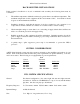
DTS-6 Installation Manual IV. Section 4: Checkout and Adjustment CHECKOUT AND ADJUSTMENT PROCEDURE A SPL meter and the DTS technician’s kit (not included with the DTS system) are required to complete the checkout and adjustment procedure. The technician’s kit consists of: - a DTS 6-track Rev.
DTS-6 Installation Manual Section 4: Checkout and Adjustment The DTS 6-CHANNEL SETUP DISC, Rev. C contains the following signals: • 1 kHz at reference level. All five channels • 30 Hz tone at reference level. Sub bass channel.
DTS-6 Installation Manual Section 4: Checkout and Adjustment 6-TRACK STEREO LEFT LEVEL LEFT LEFT HF LEFT SURR RIGHT LEVEL CENTER RIGHT HF RIGHT SURR STEREO SUBWOOF RIGHT 6-TRACK SUBWOOF MONO SURR .
DTS-6 Installation Manual 4.2 Section 4: Checkout and Adjustment Timecode Reader Adjustment. See Figure 4. • Eject the SETUP DISC and insert the DTS 6-TRACK DEMONSTRATION D-1 disc. Thread the DEMO REEL through the projector and the DTS reader head. • The DEMO REEL has a specially printed leader for setting the timecode head offset. Start with the offset measurement start mark, “00”, at the timecode head’s red LED (inside the lens).
DTS-6 Installation Manual Section 4: Checkout and Adjustment 4-5
DTS-6 Installation Manual V Section 5: Operation OPERATION • Threading Timecode Reader: Refer to Figure 5. Make the same size loops through the projector as you did when checking the offset number. • Verifying Movie Discs Make sure your discs match the movie (e.g. “Jurassic Park” film with “Jurassic Park” movie discs). If the film and discs don't match the digital sound track will not play.
DTS-6 Installation Manual Section 5: Operation • The DTS “Stand Alone Trailer” Disc Do NOT insert the “Stand Alone Trailer Disc” into the DTS-6 with any movie disc. This will cause the DTS-6 to malfunction. This disc is meant to be used when the DTS and THX trailers are attached to a non-DTS feature. All current DTS movie discs contain the DTS and THX trailers. To verify that these trailers are on your movie discs, look to the right of the movie title.
DTS-6 Installation Manual Section 5: Operation • Maintenance The timecode reader lens should be blown off with compressed air once a day to remove any dust build up. The CD-ROM drives do not have to be cleaned, but keep their doors shut as to keep dust out. • After The Show When returning a DTS encoded movie back to the distributor, put the movie discs back into the yellow reel. Put the loaded yellow reel in the can with the film.
DTS-6 Installation Manual Section 5: Operation • How DTS Effects other Cinema Processors Dolby CP200 Operation The automation should set the CP200 processor’s optical default to either “04” A-type or “05” SR . When the DTS switches to digital, the normal signal paths of the CP200 are interrupted. The DTS-6 signals will be inserted just prior to the CAT64 EQ cards, in effect taking over the CP200.
DTS-6 Installation Manual VI Section 6: Troubleshooting TROUBLESHOOTING INSIDE THE DTS-6. See Figure 6 • D-426 TRANSFORMER BOARD See drawing D426. Located on this board is the 50-pin output connection, transformers, relays, and split/mono surround switches. Output of all channels leave from this card. Subwoofer is also carried on the “stereo” cable. The newest boards have three dip switches, all grouped together and located towards the top and rear of the board.
DTS-6 Installation Manual Section 6: Troubleshooting • D-422 TIMECODE BOARD See drawing D422. This board has the timecode head offset switches, the four system status LED lights, a 7-position programming header, a 15-pin time-code cable output connector, an EPROM chip, a ROM-DOS chip, an indexing switch, and 5V fuse. - The OFFSET switches are adjusted according to the timecode reader location. This setting is different depending on type of projector or location of the timecode reader.
DTS-6 Installation Manual Section 6: Troubleshooting 6-3
DTS-6 Installation Manual Section 6: Troubleshooting 6-4
DTS-6 Installation Manual Section 6: Troubleshooting 6-5
DTS-6 Installation Manual Section 6: Troubleshooting 6-6
DTS-6 Installation Manual Section 6: Troubleshooting 6-7
DTS-6 Installation Manual Section 6: Troubleshooting EXTERNAL CABLE ASSEMBLIES • 6-Track Cable Assembly - D434 The 6-track cable is broken into three parts: JM11, JM21, BS22. The white dot on plugs indicate pin 1. - JM11 is used as an input from other sound sources (such as the CP200 pass through) to the DTS-6. This includes other digital sound sources such as Dolby SR-DTM. - JM21 is used as an output from the DTS-6. When the DTS-6 is playing in digital, only the DTS-6 output appears at JM21.
DTS-6 Installation Manual Section 6: Troubleshooting 6-9
DTS-6 Installation Manual Section 6: Troubleshooting 6-10
DTS-6 Installation Manual Section 6: Troubleshooting 6-11
DTS-6 Installation Manual Section 6: Troubleshooting 6-12
DTS-6 Installation Manual Section 6: Troubleshooting TROUBLESHOOTING TIPS Its always a good idea to stand in the theater and listen to the first few minutes of the movie. Listen to the sound level and general quality of the sound. The sound track should be in sync with the picture (wait for a dialogue scene) and played at a comfortable level. Even though not every scene will have surround material, do your best to listen for the surround speakers. Most opening musical sequences have surround information.
DTS-6 Installation Manual Section 6: Troubleshooting • Switches out of DTS digital (continued) - If the TIMECODE LED on the DTS-6 or reader head is blinking, gently squeeze the film between two fingers as it exits the reader head. Do the same at the entrance of the reader. If the LED stops blinking and maintains a steady glow, this indicates that you need to add more tension.
DTS-6 Installation Manual VII Section 7: Diagrams INSTALLATION DIAGRAMS The diagrams on the following pages cover most installations. Contact DTS if the system you are installing into does not appear. 70 MM spacer kits available, contact DTS. Brackets for the DTS Timecode Reader Head • D614 - Standard Bracket For projectors: Century, Simplex, and Cinemeccanica with Kelmar bracket (below). Intended to fit between the projector and reel arm.
DTS-6 Installation Manual Section 7: Diagrams 7-2
DTS-6 Installation Manual Section 7: Diagrams 7-3
DTS-6 Installation Manual Section 7: Diagrams 7-4
DTS-6 Installation Manual Section 7: Diagrams Wiring Diagrams Cinema Processor To DTS-6 Serial Number 2000+ 7-5
DTS-6 Installation Manual Section 7: Diagrams 7-6
DTS-6 Installation Manual Section 7: Diagrams 7-7
DTS-6 Installation Manual Section 7: Diagrams 7-8
DTS-6 Installation Manual Section 7: Diagrams 7-9
DTS-6 Installation Manual Section 7: Diagrams 7-10
DTS-6 Installation Manual Section 7: Diagrams 7-11
DTS-6 Installation Manual Section 7: Diagrams 7-12
DTS-6 Installation Manual Section 7: Diagrams 7-13
DTS-6 Installation Manual Section 7: Diagrams 7-14
DTS-6 Installation Manual Section 7: Diagrams 7-15
DTS-6 Installation Manual Section 7: Diagrams 7-16
DTS-6 Installation Manual Section 7: Diagrams 7-17
DTS-6 Installation Manual Section 7: Diagrams DTS-6 and DTS-6D to Dolby CP650 Using the D715 Logic Interface Board ! DTS D715 operation with DTS-6D (3-drives) and Dolby CP650 Connect D715-J18 to the CP650 “AUTOMATION” connector. A 25-pin cable connects the DTS-6D AUTOMAION to D715 on J1. If using the CP650 remote fader, use the DTS E322 extender to lift D715 away from the rear panel and give clearance to the remote fader connector.
DTS-6 Installation Manual Section 7: Diagrams 7-19
DTS-6 Installation Manual Section 7: Diagrams 7-20
DTS-6 Installation Manual Section 7: Diagrams WIRING DIAGRAMS FOR DTS-6 UNITS SERIAL NUMBER 1 - 1000 7-21
DTS-6 Installation Manual Section 7: Diagrams 7-22
DTS-6 Installation Manual Section 7: Diagrams 7-23
DTS-6 Installation Manual Section 7: Diagrams 7-24
DTS-6 Installation Manual Section 7: Diagrams TECHNICAL UPDATE FOR DTS TO DOLBY CP-55 / WITH AUTOMATION At the end of the show when the automation pulses the processor to non-sync it will occasionally switch back to 04 optical causing the tail end of the film to be heard as it runs out of the projector. To prevent this from occurring it will be necessary to replace the small board D-431.
DTS-6 Installation Manual Section 7: Diagrams 7-26
DTS-6 Installation Manual Section 7: Diagrams TECHNICAL UPDATE FOR DTS TO DOLBY CP-65 / WITH AUTOMATION At the end of the show when the automation pulses the processor to non-sync it will occasionally switch back to 04 optical causing the tail end of the film to be heard as it runs out of the projector. To prevent this from occurring it will be necessary to replace the small board D-431. This new card also features a selectable “SR” or “A” type back-up switching feature.
DTS-6 Installation Manual Section 7: Diagrams 7-28
DTS-6 Installation Manual Section 7: Diagrams 7-29
DTS-6 Installation Manual Section 7: Diagrams 7-30
DTS-6 Installation Manual Section 7: Diagrams OTHER HELPFUL DOCUMENTS 7-31
7-32 Revised: February 24, 1999 Digital Theater Systems 5171 Clareton Drive Agoura Hills, CA 91301 PH: 818-706-3525 Fax: 818-706-1868 2 9 8 .6 M ILS 304 MILS +2/-0 PICTURE APERTURE EDGE REFEREN C E ED G E TIM E C O D E TR A C K 0.5 MILS 2.0 MILS 298.6 MILS PRINT TOLERANCE NEGATIVE TOLERANCE REFERENCE EDGE TIME CODE STARTS 4 PERFS AFTER SYNC POP START ( -0.5/+1.
DTS-6 Installation Manual Section 7: Diagrams DTS EMPIRICAL TEST DISC Test #1 will play automatically. To proceed, wait for the announcement, then select the desired test number on the TIMECODE HEAD OFFSET rotary switches (located behind the player's front panel access cover). Be sure to write down the current offset setting before your selection is made and restore the setting for proper DTS movie playback.
DTS-6 Installation Manual Section 7: Diagrams DTS-6 System Parts List D431-00 D490-00 D496-00 D497-00 D715 Logic break-out board (generic / test board, Odyssey system) Logic break-out board (Dolby CP55) Logic break-out board (Dolby CP65) Logic break-out board (UltraStereo) Logic break out board (Dolby CP500) D437-00 D437-01 D458-00 D458-01 9030-DT10-00 Audio break-out board (generic / test board) Audio break-out board (Dolby CP55, CP65) Audio break-out board (Dolby CP50) Audio break-out board (Dolby CP
DTS-6 Installation Manual Section 7: Diagrams 7-35
DTS-6 Installation Manual Section 7: Diagrams Dual Projector Theaters Guide For A Seamless Change-Over Occasionally, when running a DTS movie with dual projectors, you may come across situations when the picture and sound are not changing in unison during a change over. This is due to the fact that as soon as the first frame of action reaches the picture aperture on the incoming projector, the DTS digital sound will change over to that reel.
DTS-6 Installation Manual Section 7: Diagrams 7-37
DTS-6 Installation Manual Section 7: Diagrams DTS MARQUEE SIGN ORDER FORM For every DTS-6 system in the field, we will provide marquee signs and one-sheet DTS posters at no charge. Please fill out the following information and these will be shipped within 2-3 weeks of receipt of the order form. We will send the items directly to the theatre, or to the dealer for distribution. If we send the marquees directly to the dealer, we need to know the names and locations of the theatres for our records.
DTS-6 Installation Manual Section 7: Diagrams Notice to Field Technicians Subject: UltraStereo Interface to DTS-6 July 24, 1995 A problem has been identified in the UltraStereo DTS-10B board. The UltraStereo audio breakout board, DTS-10B, has the left surround and the mono surround outputs tied together. This lowers the left surround’s output level and rolls off its high end when the DTS-6 is set for split (stereo) surrounds. Only the DTS-10B (shown below), WITH NO REV. LETTER, requires modification.
DTS-6 Installation Manual Section 7: Diagrams NOTES Thank you for choosing DTS ! 7-40