
Installation manual


DTS-6 Installation Manual Section 3: Installation Procedure
3-2
3.2 DTS-6 Processor Installation
DTS has configured your DTS-6 processor to interface to the cinema processor as indicated
on the packing list. A DTS-6 labeled “generic” will be set for stereo surrounds, subwoofer-
disable turned off, and platter (single projector) operation. If the DTS-6 processor you are
about to install did not come from the factory then you will need to check some internal
switches.
** Be sure the rear panel AC voltage switch is properly set for your mains
AC supply rating **
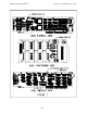
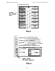
Remove the top cover. See Figure 1.
Programming the Surrounds
The transformer board, D426, that is mounted to the left of the unit must be set for either
split surround or mono surround operation. Current boards have toggle dip switches near
the top of the unit. Toggling all these switches up is for split surround and toggling
them all down is for mono surround operation. If your transformer board does not have
dip switches then there are three shunts that have to be set. All three locations are clearly
marked split or mono. Place the shunt over the middle pin and split pin for split surround
operation, or the middle pin and mono pin for mono surround operation. See D426
transformer card diagram for details.
Programming the Subwoofer Output at the Stereo Cable
Locate the playback card D420 REV E (the card with the 15-pin D-connector on rear
panel). To ensure the subwoofer signal always appears at the stereo cable:
- DTS-6 units with serial number 2000 or over, set both dip switches at the top of the
board (S1) to the following: S1-#1 OFF (open) towards the board and S1-#2 ON
(closed) away from the board. Setting S1-#1 ON will cause the subwoofer signal to not
appear at the stereo cable. S1-#2 is no longer used.
- DTS-6 units with serial number 1000 or under, be sure no shunt appears across J6.
Putting a jumper across J6 will cause the subwoofer signal to not appear at the stereo
cable.
Programming for Change-over Operation
Locate the timecode board D422 (the card with the 9-pin D-connector on the rear panel
and LED's on the front). Near top center of the board there is a 7-position header. A
shunt is required vertically over position “0” (farthest right position) if you are installing
for change-over operation. Remove this shunt for platter house operation.
Reinstall top cover.