
Installation manual


DTS-6 Installation Manual Section 3: Installation Procedure
3-4
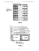
The DTS-6 Processor
• The DTS-6 processor is designed to be integrated into your existing theater sound system
without affecting normal theater operation. All interconnects are stand-alone. No cuts or
jumpers are necessary on most systems.
• DTS-6 processor requires 5 1/4" tall by 17" deep of 19" wide rack space for proper
mounting. Select a space in the sound rack not more than three feet from the existing
*cinema processor to be interconnected. Bolt the DTS processor into the rack. Be sure to
observe ventilation requirements specified in the beginning of this book.
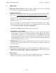
• Check that the DTS-6 front panel power switch is in the OFF position.
• Connect the power cable to the DTS-6 processor. (NOTE: The DTS-6 processor is a
computer based system and as such can be susceptible to power line surges. A quality
surge/spike suppresser made for computers is recommended.
• Connect the 9-pin cable (P/N D435) from the timecode reader head to the back of the
DTS-6 processor.
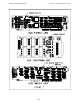
• Refer to wiring drawings in Section VIII that relates to your specific installation. Connect
the DTS-6 50-pin cable (P/N D434) into your cinema sound system / processor.
• The 15-pin “stereo” cable is used for some installations. It is used to route the DTS-6
subwoofer output to the subwoofer amplifier. It is used with the Dolby CP200, CP55,
and some UltraStereo processors. Other cinema processors use the other DTS subwoofer
output at the 50-pin connector (JM21). See Section VIII “Wiring Diagrams” and find the
diagram that pertains to your installation.
• You may connect the DTS-6 into other digital playback sound systems. You may obtain
the necessary adapters from DTS.
-- for a CP200 with SR-D
TM
, use the D462 cable
-- for a CP65 with SR-D
TM
, use the D462-01 cable
-- for a CP500, use the D561 cable and the D715 board.
See Section VIII “Wiring Diagrams” for installation details.
REMEMBER
** Be sure the rear panel AC voltage switch is properly set for your main AC
supply rating **