
Installation manual

DTS-6 Installation Manual Section 6: Troubleshooting
6-2
•
••
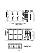
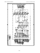
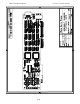
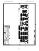
• D-422 TIMECODE BOARD
See drawing D422. This board has the timecode head offset switches, the four system
status LED lights, a 7-position programming header, a 15-pin time-code cable output
connector, an EPROM chip, a ROM-DOS chip, an indexing switch, and 5V fuse.
- The OFFSET switches are adjusted according to the timecode reader location. This setting is
different depending on type of projector or location of the timecode reader. Determining the
offset setting is done with either frames count method or using the DTS leader from the
Demo Film.
- The status LED lights:
SYSTEM light flashes when the DTS-6 is ready to play, TIMECODE
lights if good timecode is being read, DIGITAL lights when the DTS-6 is playing in digital,
and
CD-ROM lights if the drives are recognized and the discs are being read.
- The 7-position header has jumper settings for different functions, most common is the setting
for single projector operation. For this, the jumper is in a holder position which is across top
part of the header, set horizontally between the “4” and “0”. For dual projector operation
the jumper is set vertically on the “0” position.
- The 15-pin connector is there for the “stereo” cable to plug into. The stereo cable is currently
being used for subwoofer output only.
- The EPROM stores part of the operating software information while the rest is on the movie
disc(s).
- The ROM-DOS is located near the center bottom of the board When updating the CD-ROM
drives from 2X to 4X, the ROM-DOS chip has to be replaced to Rev. C. When replacing
with TEAC drives, contact DTS.
- The index switch, located below the offset switches, can be used to advance though the
individual channel pink noise tests on the DTS “REV C” Setup Disc. It can also be used to
force the DTS-6 (when playing in digital) to optical for as long as the button is held down.
- The 5V replacable fuse protects the power going to the DTS timecode reader head.
•
••
• POWER SUPPLY - Supplies power to the DTS-6 unit. Caution, be sure to check
that the proper AC voltage is selected on the supply for your installation.
•
••
• SCSI BOARD - Controls the CD-ROM drives.
•
••
• CD-ROM DRIVES - There are two CD-ROM drives in the DTS-6. Both are the
same with exception of the way top and bottom drive program jumpers are installed and
if terminating resistors are added Contact DTS for more information.
The lights on the two CD-ROM drives will flash when the drives are recognized during
the test cycle (after power-up) or when the movie discs are being read.