
Installation manual


DTS-6 Installation Manual Section 7: Diagrams
7-18
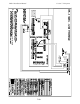
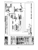
DTS-6 and DTS-6D to Dolby CP650 Using the D715 Logic Interface Board
!
!!
! DTS D715 operation with DTS-6D (
3-drives
) and Dolby CP650
Connect D715-J18 to the CP650 “
AUTOMATION
” connector. A 25-pin cable connects the DTS-6D
AUTOMAION
to D715 on J1. If using the CP650 remote fader, use the DTS
E322
extender to lift
D715 away from the rear panel and give clearance to the remote fader connector.
D715 board:
W5
and
J2
are used only for DTS-6 applications and J6 is a pass-through connection
for automation.
When the DTS-6D switches into digital, it sends a format pulse to the CP650 “
AUTOMAION
“
connector on pin 5 (
Format 11 “external 6-channel analog” = DTS
) which engages button “11” on the
front panel.
When the DTS-6D drops out of digital, it will send
1
of
4
(
fallback
) pulses to the CP650. The D715
logic board has jumpers that “steer” each default pulse to one of several CP650 format keys.
The
MONO, A-TYPE (“A”)
, and SR pulses are sent by the DTS-6D. They are programmed on the
DTS movie disc(s) and are used to return the CP650 back to the optical format the movie was
recorded in. The
NONSYNC
(“
NS”
) pulse (
from the DTS-6D
) will be sent if DTS timecode is lost
during the last 60 seconds of the last reel.
SETTING FORMAT JUMPERS
MONO
jumper - place jumper horizontally across
SK1
(‘01’ button)
NS jumper - place jumper between center pin and
SK7
(“NS” button)
SR jumper - place jumper between center pin and
SK3
(“05” button)
“A” jumper - place jumper between center pin and
SK2
(“04” button)
! DTS D715 operation with DTS-6 (
2-drives
) and Dolby CP650
Connect D715-J18 to the CP650 “
AUTOMATION
” connector. The DTS-6 “BS22” 10-pin connector
(
on the 50-pin cable
) connects the DTS-6 logic to D715 on J2. Note pin 1 for proper orientation. If
using the CP650 remote fader, use the DTS
E322
extender to lift D715 away from the rear panel and
give clearance to the remote fader connector.
D715 board:
J1
is normally used only for DTS-6D applications and
J6
is a pass-through connection
for automation.
When the DTS-6 switches into digital, it sends a format pulse to the CP650 “
AUTOMAION
“
connector on pin 5 (
Format 11 “external 6-channel analog” = DTS
) which engages button “11” on the
front panel.
W5 must be installed
for “fallback” operation
(
use jumper from “SR” or “NS” header
)
with the DTS-6
.
When W5 is installed and the DTS-6 drops out of digital, a single “fallback” pulse will be sent to the
CP650. The D715 board’s “
A
” 3-pin header “steers” the pulse to either
SK2
(A
-TYPE = “04” button
)
or
SK3
(
SR = “05” button
). The user must select which format is desired and selection is made with a
jumper from the center pin to the optical sound format the movie was recorded (most cases =
SR)
.