
Installation manual


DTS-6 Installation Manual Section 7: Diagrams
7-27
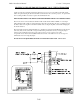
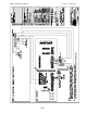
TECHNICAL UPDATE FOR DTS TO DOLBY CP-65 / WITH AUTOMATION
At the end of the show when the automation pulses the processor to non-sync it will occasionally switch
back to 04 optical causing the tail end of the film to be heard as it runs out of the projector. To prevent this
from occurring it will be necessary to replace the small board D-431. This new card also features a
selectable “SR” or “A” type back-up switching feature. In addition the new card will accept the SR-D sense
control plug.
To install the D-496 board on the CP-65, remove the cover off the J-18 pin connection on the back plane.
Plug the new card directly into the J-18 socket of the CP-65. Plug the SR-D sense control into conn 2 of the
new board. (If you are equipped with SR-D) If you are not equipped with an SR-D unit simply cover conn
3 with the cover that was removed from the back plane of J-18. Next remove DTS cable BS-22 from old
logic board D-431 and install cable on conn 3 of the new board. *Note on some 50 pin cables the
BS-22 ribbon cable is soldered directly to the d-431 card. If this is the case you will need to cut the ribbon
cable removing D-431 then install the enclosed 10-pin IDC socket which will plug into the new D-496
board. Make sure BS-22 is plugged in correctly. See diagram.
IF YOU HAVE ANY QUESTIONS PLEASE CALL DTSFOR ASSISTANCE. 818-706-3525