
Service manual

- 13 -
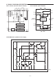
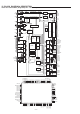
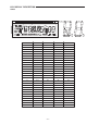
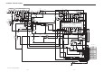
IC BLOCK DIAGRAM & DESCRIPTION
IC601 IC LC72338-9B55 (Single-Chip PLL + Controller)
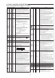
PIn name Pin No. I/O I/O Format Functions
S17/PE0
S18/PE1/SCK2
S19/PE2/SO2
S20/PE3/SI2
S25/PM0
S26/PM1
S27/PM2
S28/PM3
39
38
37
36
30
29
28
27
I/O
I/O
LCD driver segment output, general-porpose input/output and
serial I/O ports
The IOS instruction is used to switch between the LCD driver
segment output, general-purpose I/O, and serial I/O functions,
and to switch between input and output of the general-purpose
input port function.
• For use as segment output
These pins can be set in bit units.
The IOS instruction with Pn=ODH specifies segment output
use in bit units.
b0=S17/PE0 0 • • • Segment output
b1=S18/PE1 1 • • • PE0 to 3 output
b2=S19/PE2
b3=S20/PE3
• For use as general-purpose input /output port
These pins can be set for input /output in bit units.
(1 bit I/O)
b2=SI/O2 0 • • • Genetal-purpose port
1 • • • SI/O port
Input /output is specified with the IOS instruction in bit units.
PE • • • Pn=4 0 • • • Input
1 • • • Output
• For serial I/O port
The serial I/O port function is specified with the IOS instruction
(Pn=0).
The contents of the serial I/O data buffer can be saved and
loaded with the INR and OUTR instructions.
*Pin setup states when used as a serial I/O port
PE0 • • • General-purpose input /output
PE1 • • • SCK2 output in internal clock mode
SCK2 output in external clock mode
PE2 • • • SO2 output
PE3 • • • SI2 input
In CLOCK STOP mode, if this port is used as a general-purpose
I/O port or as a serial I/O port, the pins go to the input disabled
high-impedance state. If used for segment output, the pins fixed at
the low level. The segment output port function is selected after a
power-on reset.
LCD driver segment output, general-porpose input /output ports.
The IOS instruction is used to switch between the LCD driver
segment output, general-purpose I/O port, and serial I/O to switch
between input and output of the general-purpose input /output
port function.
• For use as segment output
These pins can be set in 4 bits units. The IOS instruction with
Pn=OEH specifies segment output use in bit units.
b0=S25 to 28/PM0 to 3 0 • • • Segment output
1 • • • PM0 to 3
• For use as general-purpose input /output port
These pins can be set for input /output in bit units.
Input /output is specified with the IOS instruction in bit units.
PM • • • Pn=OCH 0 • • • Input
1 • • • Output
In CLOCK STOP mode, if this port is used as a general-purpose
I/O port, the pins go to the input disabled high-impedance state. If
used for segment output, the pins are fixed at the low level. The
segment output port function is selected after a power-on reset.
CMOS
three
value
output
and
push-pull
CMOS
three
value
output
and
push-pull
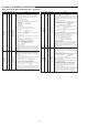
PIn name Pin No. I/O I/O Format Functions
S21/PF0
S22/PF1/SCK1
S23/PF2/SO1
S24/PF3/SI1
S29/PN0/BEEP
S30/PN1
S31/PN2
S32/PN3
35
34
33
32
26
25
24
23
I/O
O
LCD driver segment output, general-porpose input/output and
serial I/O ports.
The PF0 to 3 inputs are in the Schmidt format.
The IOS instruction is used to switch between the LCD driver
segment output, general-purpose I/O, and serial I/O functions, and
to switch between input and output of the general-purpose input
port function.
• For use as segment output
These pins can be set in 4 bits units. The IOS instruction with
Pn=OEH specifies segment output use in bit units.
b0=S21 to 24/ PF0 to 3 0 • • • Segment output
1 • • • PE0 to 3
• For use as general-purpose input /output port
These pins can be set to input /output in bit units. (1 bit I/O)
b1=SI/O 1 0 • • • Genetal-purpose port
1 • • • SI/O port
Input /output is specified with the IOS instruction in bit units.
PF • • • Pn=5 0 • • • Input
1 • • • Output
• For use as serial I/O port
The serial I/O port function is specified with the IOS instruction
(Pn=0). The contents of the serial I/O data buffer can be saved
and loaded with the INR and OUTR instructions.
*Pin setup states when used as a serial I/O port
PF0 • • • General-purpose input /output
PF1 • • • SCK1 output in internal clock mode
SCK1 output in external clock mode
PF2 • • • SO1 output
PF3 • • • SI1 input
In CLOCK STOP mode, if this port is used as a general-purpose
I/O port or as a serial I/O port, the pins go to the input disabled
high-impedance state. If used for segment output, the pins are
fixed at the low level. The segment output port function is selected
after a power-on reset.
Segment output/general-porpose input port 1/ BEEP tone output
pins. The IOS instruction is used to switch between the segment
output port and the PN0 to 3 functions. The BEEP instruction
switches between the general-purpose output port and BEEP tone
function.
• For use as segment output
These pins can be set in 3 bits units. The IOS instruction with
Pn=OEH specifies segment output use in bit units.
b2=S29 to 32/ PN0 to 3 0 • • • Segment output
1 • • • PN0 to 3
• For use as general-purpose output.
The general-porpose output port function is selected with the
BEEP instruction (b3=0).
PN1 to 3 are dedicated general-purpose output function pins.
• For use as BEEP output pin
The BEEP instruction with b3=1 sets the BEEP output.
The BEEP instruction bit b0,b1 and b2 sets the frequency.
When this is set as the BEEP port, executing an output
instruction will rewrite the internal latch data but has no
influence on the output.
These pins go to the output high-impedance state in clock stop
mode. If used for segment output, the pins are fixed at the low level.
These pins go to the output high-impedance state during the
power-on reset and hold that state until an output instruction is
executed.
CMOS
three
value
output
and
push-pull
CMOS
three
value
output
and
push-pull