XPA2500 XPA4640 XPA SERIES INSTALLATION/OWNER’S MANUAL Mobile Power Amplifiers
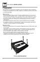
XPA SERIES INSTALLATION Preparation Please read entire manual before installation. Due to the technical nature of amplifiers, it is highly recommended that your DUAL amplifier is installed by a professional installer or an authorized dealer. Before You Start • Disconnect negative battery terminal.
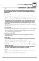
XPA SERIES INSTALLATION Connection Descriptions NOTE Be sure to follow specific instructions included with your amplifier installation kit (not included with this amplifier). The information below should be used a general guideline only. Power Wire (+12V) • Disconnect negative battery terminal before proceeding. Consult a qualified technician for instructions if you are unsure. • Plan wire routing before cutting any wires to length.
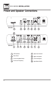
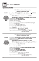
XPA SERIES INSTALLATION Power and Speaker Connections XPA2500 1 2 3 4 5 6 7 2 3 4 5 6 7 8 XPA4640 4 1 7 1 LED Indicator 5 Input Level Control 2 Bass Boost 6 High Level Inputs 3 Crossover Mode Switch 7 Low Level Inputs 4 Crossover Frequency 8 Input Mode Switch
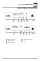
XPA SERIES INSTALLATION Audio Inputs and Controls 1 1 2 4 3 5 4 XPA2500 5 3 2 XPA4640 1 Speaker Connection(s) 4 +12VDC Battery Connection 2 Ground Connection 5 Fuse(s) 3 Remote Connection 5
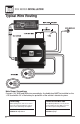
XPA SERIES INSTALLATION Typical Wire Routing Main Power Connections Connect +12V, GND and REM wires accordingly. A suitable fuse MUST be installed on the +12V lead within 18" of the battery for protection of the vehicle’s electrical system. 6 Fuse Rating Power/Ground Wire Size When replacing fuses, make sure new fuse is the correct type and amperage. Using an incorrect fuse could damage the amplifier. For optimum performance, use only the wire size listed below or larger.
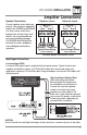
XPA SERIES INSTALLATION Amplifier Connections Speaker Connections Connect speaker wires observing polarity. The minimum impedance load for the XPA2500 and XPA4640 is 2 ohms stereo and 4 ohms bridged. Use of loads lower than these is not recommended and may cause amplifier damage. The XPA2500 and XPA4640 can be wired for stereo, bridged or stereo/bridged simultaneous operation.
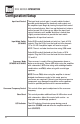
XPA SERIES OPERATION Configuration/Setup Input level Control The input level control (gain) is used to obtain the best possible match between the head unit audio output and the amplifier input. Begin by turning the input level control fully counterclockwise. Next, turn up the head unit volume control around 3/4 of the way up. Adjust the input level control clockwise until audible distortion is heard, then slightly counterclockwise to provide the best match. Repeat for all input level controls.
XPA SERIES WARRANTY Limited One-Year Warranty This warranty gives you specific legal rights. You may also have other rights which vary from state to state. Dual Electronics Corp. warrants this product to the original purchaser to be free from defects in material and workmanship for a period of one year from the date of the original purchase. Dual Electronics Corp.
XPA SERIES OPERATION Specifications CEA-2006 Power Standard Specifications (reference: 14.
XPA SERIES OPERATION Notes 11
XPA SERIES OPERATION Troubleshooting Problem Cause Action Unit will not turn on +12V wire not connected or incorrect voltage Check connections for proper voltage (no power LED indicator) REM wire not connected or incorrect voltage (11~16VDC) GND wire not connected Check connection to ground Fuse(s) blown Unit has power - LED is Speaker wires not connected green (but no sound) Volume turned all the way down One or more speaker wires touching each other or touching chassis ground Speaker(s) defective or d