R-1600 R-1601 R-1602 SERVICE MANUAL S4910R1600X// OVER THE RANGE MICROWAVE OVEN MODELS TURNTABLE SENSOR DEFROST BREAK FAST POPCORN 1 Baked potatoes 2 Fresh vegetables 3 Frozen vegetables 4 Rice 5 Ground meat 6 Fish/Seafood 7 Chicken breasts 8 Turkey breast 9 Roast pork 0 Meat loaf DINNER 2 7 4 9 3 8 CUSTOM HELP MINUTE PLUS 1 Dinner plate 2 Pasta/casserole 3 Frozen entree 4 Frozen snack 5 Pizza, slice LUNCH 1 6 HELP OFF COOK 1 Coffee/tea 2 Roll/muffin, fresh 3 Roll/muffin, frozen 4 Hot cereal
R-1600 R-1601 R-1602 PRECAUTIONS TO BE OBSERVED BEFORE AND DURING SERVICING TO AVOID POSSIBLE EXPOSURE TO EXCESSIVE MICROWAVE ENERGY (a) Do not operate or allow the oven to be operated with the door open.
R-1600 R-1601 R-1602 WARNING TO SERVICE PERSONNEL Microwave ovens contain circuitry capable of producing very high voltage and current, contact with following parts may result in a severe, possibly fatal, electrical shock. (Example) High Voltage Capacitor, High Voltage Power Transformer, Magnetron, High Voltage Rectifier Assembly, High Voltage Harness etc.. Read the Service Manual carefully and follow all instructions. Don't Touch ! Danger High Voltage When the testing is completed, 1.
R-1600 R-1601 R-1602 MICROWAVE MEASUREMENT PROCEDURE A. Requirements: 1) Microwave leakage limit (Power density limit): The power density of microwave radiation emitted by a microwave oven should not exceed 1mW/cm2 at any point 5cm or more from the external surface of the oven, measured prior to acquisition by a purchaser, and thereafter (through the useful life of the oven), 5 mW/cm2 at any point 5cm or more from the external surface of the oven.
R-1600 R-1601 R-1602 SERVICE MANUAL PRODUCT DESCRIPTION OVER THE RANGE MICROWAVE OVEN R-1600 / R-1601 / R-1602 GENERAL INFORMATION FOREWORD This Manual has been prepared to provide Sharp Electronics Corp. Service Personnel with Operation and Service Information for the SHARP OVER THE RANGE MICROWAVE OVEN, R-1600, R-1601, R-1602. It is recommended that service personnel carefully study the entire text of this manual so that they will be qualified to render satisfactory customer service.
R-1600 R-1601 R-1602 PRODUCT SPECIFICATION ITEM DESCRIPTION Power Requirements 120 Volts / 14 Amperes 60 Hertz Single phase, 3 wire grounded Power Output 1.6 Cubic Feet 1000 watts (IEC-705 TEST PROCEDURE) Operating frequency of 2450MHz Width 29-15/16" Height 16-3/8" Depth 15- 1/16" (Not including the door handle) Width 21" Height 8-7/8" Depth 14-7/16" Hood lamp Hood fan 2 bulbs, 20W x 2, Incandescent light bulbs Approx. 300 C.F.M.
R-1600 R-1601 R-1602 Electrical Requirements The oven is equipped with a 3-prong grounding plug. DO NOT UNDER ANY CIRCUMSTANCES CUT OR REMOVE THE GROUNDING PIN FROM THE PLUG. The power supply cord and plug must be connected to a separate 120 Volt AC, 60 Hz, 15 Amp. or more dedicated line, using a grounded receptacle. The receptacle should be located inside the cabinet directly above the Microwave Oven/Hood system mounting location.
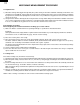
R-1600 R-1601 R-1602 CONTROL PANEL DEFROST TURNTABLE OFF COOK HELP BREAKFAST 1 Coffee/tea 2 Rolls/muffins, fresh 3 Rolls/muffins, frozen 4 Hot cereal 5 Scrambled eggs LUNCH 1 Dinner plate 2 Pasta/casserole 3 Frozen entrees 4 Frozen snacks 5 Pizza, slice DINNER 1 Baked potatoes 2 Fresh vegetables 3 Frozen vegetables 4 Rice 5 Ground meat 6 Fish/seafood 7 Chicken breasts 8 Turkey breast 9 Roast pork 0 Meat loaf 1 6 2 7 3 8 CUSTOM HELP MINUTE PLUS 4 9 POPCORN COMPU DEFROST MEMORY COOK 5 0 POWER
R-1600 R-1601 R-1602 OPERATION DESCRIPTION OF OPERATING SEQUENCE of the secondary interlock switch and primary interlock relay (RY2) and is mechanically associated with the door so that it will function in the following sequence. (1) When the door opens from a closed position, the primary interlock relay and secondary interlock switch open their contacts, and then the monitor switch contacts close.
R-1600 R-1601 R-1602 BREAKFIRST, LUNCH, DINNER 3. RE-CIRCULATION (INSIDE VENTING) The air handing is the same as VERTICAL VENTING except that the final air discharge is directed horizontally through the upper front of the oven into the kitchen. IN this case, the accessory charcoal filter RK-230 must be provided to filter the air before it leaves the oven. BREAKFIRST, LUNCH, DINNER will automatically compute the microwave power and cooking time.
R-1600 R-1601 R-1602 MAGNETRON TEMPERATURE FUSE CONTROL UNIT COM. N.O. RY4 HOOD FAN THERMAL CUT OUT RY5 High B3 N.C. GRN B1 Low E2 HOOD CAPACITOR A3 B9 A7 N.O. TTM HOOD LAMP HL A5 HL FAN MOTOR A1 TURNTABLE MOTOR HOOD MOTOR RY1 FM DOOR SENSING SWITCH RY2 HIGH VOLTAGE CAPACITOR 0.94µF COM. OL STIRRER MOTOR RY3 OVEN LAMP 120 V AC.
R-1600 R-1601 R-1602 DESCRIPTION AND FUNCTION OF COMPONENTS DOOR OPEN MECHANISM CAUTION: BEFORE REPLACING A BLOWN MONITOR FUSE TEST THE DOOR SENSING SWITCH, PRIMARY INTERLOCK RELAY (RY2), SECONDARY INTERLOCK SWITCH AND MONITOR SWITCH FOR PROPER OPERATION. (REFER TO CHAPTER "TEST PROCEDURE"). NOTE: MONITOR FUSE AND SWITCH ARE REPLACED AS AN ASSEMBLY The door is opened by pulling the door handle, refer to the Figure D-1.
R-1600 R-1601 R-1602 HOOD LAMP This air is then expelled either vertically or horizontally through the customer supplied duct system, or discharged back into the kitchen. The hood lamps are mounted at the hood lamp angle on the base cover. The hood lamps can be turned off and on by touching the WORK LIGHT pad or the NIGHT LIGHT pad. And also the brightness can be varied to high or low by touching the WORK LIGHT pad or the NIGHT LIGHT pad.
12 MICROWAVE COOKING CONDITION IDLE CONDITION POSSIBLE CASE AND DEFECTIVE PARTS OFF CONDITION E Home fuse blows when power cord is plugged into wall receptacle. Monitor fuse blows when power cord is plugged into wall receptacle. Display does not illuminate when power cord is first plugged into wall receptacle. Display does not operate properly when STOP/CLEAR key is touched. (The time of day should appear on the display with beep sound during normal condition.
R-1600 R-1601 R-1602 TEST PROCEDURES PROCEDURE LETTER A COMPONENT TEST MAGNETRON ASSEMBLY TEST 1. 2. 3. 4. 5. 6. 7. 8. 9. Disconnect the power supply cord, and then remove outer case. Open the door and block it open. Discharge high voltage capacitor. To test for an open filament, isolate the magnetron from the high voltage circuit. A continuity check across the magnetron filament leads should indicate less than 1 ohm.
R-1600 R-1601 R-1602 TEST PROCEDURES PROCEDURE LETTER COMPONENT TEST (HIGH VOLTAGES ARE PRESENT AT THE HIGH VOLTAGE TERMINAL, SO DO NOT ATTEMPT TO MEASURE THE FILAMENT AND HIGH VOLTAGE.) C HIGH VOLTAGE RECTIFIER TEST 1. 2. 3. 4. Disconnect the power supply cord, and then remove outer case. Open the door and block it open. Discharge high voltage capacitor. Isolate the rectifier from the circuit.
R-1600 R-1601 R-1602 TEST PROCEDURES PROCEDURE LETTER COMPONENT TEST 6. Reinstall the outer case (cabinet). 7. Reconnect the power supply cord after the outer case is installed. 8. Run the oven and check all functions. CAUTION: IF THE THERMAL CUT-OUT OR TEMPERATURE FUSE INDICATES AN OPEN CIRCUIT AT ROOM TEMPERATURE, REPLACE THERMAL CUT-OUT OR TEMPERATURE FUSE. F SECONDARY INTERLOCK SWITCH TEST 1. 2. 3. 4. 5. 6. 7. 8. G Disconnect the power supply cord, and then remove outer case.
R-1600 R-1601 R-1602 TEST PROCEDURES PROCEDURE LETTER COMPONENT TEST 5. 6. 7. 8. with the door opened (in this condition the plunger of the monitor switch is pushed in), the meter should indicate an open circuit. If improper operation is indicated, the switch may be defective. After testing the monitor switch, reconnect the wire lead to the monitor switch (COM) terminal and check the continuity of the monitor circuit. Reconnect all leads removed from components during testing.
R-1600 R-1601 R-1602 TEST PROCEDURES PROCEDURE LETTER COMPONENT TEST YLW 4 1 HOOD FAN CAPACITOR 32 Ω 5 Resistance between; BLU 45 Ω 20 Ω BLU (1) BLK (2) BLU (1) BLK (2) WHT (3) AND AND AND AND AND YLW (4) = YLW (4) = BLK (2) = WHT (3) = RED (5) = BLU BLK WHT 1 2 3 2 BLK RED 3 0Ω (Shorted) 32Ω 32Ω 20Ω 45Ω 6-PIN CONNECTOR OF HOOD FAN MOTOR WHT 5. 6. 7. 8. L Reconnect all leads removed from components during testing. Reinstall the outer case (cabinet).
R-1600 R-1601 R-1602 TEST PROCEDURES PROCEDURE LETTER COMPONENT TEST 6) Re-install the outer case (cabinet). 7) Reconnect the power supply cord after the outer case is installed. 8) Run the oven and check all functions. 2. Control Unit. The following symptoms indicate a defective control unit. Before replacing the control unit, perform the Key unit test (Procedure M) to determine if control unit is faulty. 2-1 In connection with pads.
R-1600 R-1601 R-1602 TEST PROCEDURES PROCEDURE LETTER N COMPONENT TEST RELAY TEST 1. 2. 3. 4. 5. Disconnect the power supply cord, and then remove outer case. Open the door and block it open. Discharge high voltage capacitor. Disconnect the leads to the primary of the power transformer. Ensure that these leads remain isolated from other components and oven chassis by using insulation tape. 6. After that procedure, re-connect the power supply cord. 7.
R-1600 R-1601 R-1602 TEST PROCEDURES PROCEDURE LETTER COMPONENT TEST STEPS 1 2 OCCURRENCE CAUSE OR CORRECTION Only pattern at "a" is broken. Pattern at "a" and "b" are broken. RY3 (J1) 1 c 7 b a d P 5) Make a visual inspection of the varistor. Check for burned damage and examine the transformer with a tester for the presence of layer short-circuit (check the primary coil resistance which is approximately 780Ω ± 10%). If any abnormal condition is detected, replace the defective parts.
R-1600 R-1601 R-1602 TOUCH CONTROL PANEL ASSEMBLY OUTLINE OF TOUCH CONTROL PANEL The touch control section consists of the following units as shown in the touch control panel circuit. 7) Relay Circuit To drive the magnetron, fan motor, stirrer motor, turntable motor, hood motor, and light the oven lamp and hood lamp.
R-1600 R-1601 R-1602 DESCRIPTION OF LSI LSI(IZA958DR) The I/O signal of the LSI(IZA958DR) is detailed in the following table. Pin No. Signal I/O 1 AN10 IN Signal coming from touch key. When either G10 line on key matrix is touched, a corresponding signal out of P10, P11, P12, P13, P14 and P17 will be input into AN10. When no key is touched, the signal is held at "H" level. 2 AN11 IN 3 AVSS IN Signal similar to AN10.
R-1600 R-1601 R-1602 Pin No. 24 Signal P25 I/O OUT Description Magnetron high-voltage circuit driving signal. To turn on and off the cook relay(RY2). In P-HI operation, the signals holds "L" level during microwave cooking and "H" level while not cooking. In other cooking modes (P-90,P-80,P-70,P-60,P50,P-40,P-30,P-20,P-10,P-0) the signal turns to "H" level and "L" level in repetition according to the power level. 25 26 27 P26 P27 P30 OUT OUT OUT VARI-MODE P-HI (100% power) P-90 (approx.
R-1600 R-1601 R-1602 Pin No. Signal I/O AVCC IN AN0-AN1 IN A/D converter power source voltage. The power source voltage to drive the A/D converter in the LSI. Connected to GND. Terminal not used. AN2 IN To input signal which communicates the door open/close information to LSI. AN3 IN Door closed; "H" level signal(0V). Door opened; "L" level signal(-5V). Terminal not used. AN4-AN7 IN Terminal to change cooking input according to the Model.
R-1600 R-1601 R-1602 SERVICING 1. Precautions for Handling Electronic Components This unit uses CMOS LSI in the integral part of the circuits. When handling these parts, the following precautions should be strictly followed. CMOS LSI have extremely high impedance at its input and output terminals. For this reason, it is easily influenced by the surrounding high voltage power source, static electricity charge in clothes, etc. and sometimes it is not fully protected by the built-in protection circuit.
R-1600 R-1601 R-1602 COMPONENT REPLACEMENT AND ADJUSTMENT PROCEDURE WARNING AGAINST HIGH VOLTAGE: Microwave ovens contain circuitry capable of producing very high voltage and current, contact with following parts may result in severe, possibly fatal, electric shock. (Example) High Voltage Capacitor, Power Transformer, Magnetron, High Voltage Rectifier Assembly, High Voltage Harness etc.. WARNING: Avoid possible exposure to microwave energy. Please follow the instructions below before operating the oven.
R-1600 R-1601 R-1602 to remove. 5. Remove the louver covers A, B, and C from the hood exhaust louver ( for R-1600 only) 6. Now, the hood exhaust louver is free. REMOVAL OF OVEN FROM WALL (Two persons recommended to remove the oven) 1. Disconnect the power supply cord, and uncoil the power supply cord. 2. Remove the turntable tray and support from the oven cavity. 3.
R-1600 R-1601 R-1602 7. Remove one (1) screw holding the hood duct to the oven cavity front plate. 8. Release the 6-pin connector and the 3-pin connector of the main harness A from the hood duct. 9. Disconnect the wire leads from the fan motor and chassis support, and release the wire leads from holes of the hood duct. 10.Remove the two (2) unit mounting screws from the chassis support (right side) and the hood duct (left side). 11.Remove the one (1) screw holding the chassis support. 12.
R-1600 R-1601 R-1602 THERMAL CUT-OUT (CAVITY) REMOVAL 1. Disconnect the power supply cord and remove the oven from wall and remove outer case. (Refer to procedure of "Removal of Oven from Wall" and "Outer case Removal") 2. Open the door and block it open. 3. Discharge high voltage capacitor. 4. Remove two (2) unit mounting screws. 5. Remove the hood duct. (Refer to the procedure of " HOOD FAN MOTOR, HOOD DUCT AND OVEN LAMP SOCKET REMOVAL". 6.
R-1600 R-1601 R-1602 2. Hold the center of the bracket which supports the shaft of the fan motor on the flat table. 3. Apply the screw lock tight into the hole (for shaft) of the fan blade. 4. Install the fan blade to the shaft of fan motor by pushing the fan blade with a small, light weight, ball peen hammer or rubber mallet. 5. Install the fan motor to the hood duct with the two (2) screws. CAUTION: * Do not hit the fan blade strongly when installing because the bracket may be disfigured.
R-1600 R-1601 R-1602 CONTROL PANEL ASSEMBLY, CONTROL UNIT AND KEY UNIT REMOVAL fixing plate. 16.Release the one (1) tab holding the LCD to the LCD holder. 17.Release the four (4) tabs holding the LSI unit to the LCD holder. 18.Remove the LCD holder and the LED sheet. 19.Now, the control unit is free. 20.Remove the one (1) screw holding the key fixing plate to the control panel. 21.Release the six (6) tabs holding the key fixing plate to the control panel. 22.
R-1600 R-1601 R-1602 DOOR SENSING SWITCH, SECONDARY INTERLOCK SWITCH AND MONITOR SWITCH ADJUSTMENT 1. Disconnect the power supply cord and remove the oven from wall and remove outer case. (Refer to procedure of "Removal of Oven from Wall" and "Outer case Removal") 2. Open the door and block it open. 3. Discharge high voltage capacitor. 4. Remove the control panel assembly, referring to the procedure of "CONTROL PANEL ASSEMBLY , CONTROL UNIT AND KEY UNIT REMOVAL".
R-1600 R-1601 R-1602 Note: The door on a microwave oven is designed to act as an electronic seal preventing the leakage of microwave energy from oven cavity during cook cycle. This function does not require that door be air-tight, moisture (condensation)-tight or light-tight. Therefore, occasional appearance of moisture, light or sensing of gentle warm air movement around oven door is not abnormal and do not of themselves indicate a leakage of microwave energy from oven cavity.
1 2 3 34 CN-C N.O. RY3 N.O. COM. RY1 7 CN-A T1 1 1 4 RY2 COM. RY2 N.O. RY1 COM. RY1 N.O. C100 BLK ORG 5 ORG ORG RED BLK RED ORG RED 1 RED YLW BLK WHT CN-A 2 5 4 3 6 7 1 WHT 2 5 4 3 6 RED 8 7 N.C. BLK RED WHT N.O. COM. WHT WHT BLK GRY GRY WHT WHT FUSE & HOLDER SECONDARY INTERLOCK SWITCH COM.
R-1600 R-1601 R-1602 2 1 4 3 6 5 A A B B Q2 2SB1238 R4 27 D1-4 11ES1 1 5 D4 D3 D2 d a b + – + – R3 510 1/2w (J1) R2 560 1w c A3 OVEN LAMP FAN MOTOR SP1 PKM22EPT D23 B9 NO Q3 KRC243M RY5 + – COM B7 MICRO NO RY4 G COM C1 VA C9 VR C4 INT C11 TURNTABLE MOTOR C5 BUZZER C12 HOOD LAMP C13 HOOD MOTOR HIGH / LOW C6 A RY2 VC C5 10µ/35v D22 B5 C3 D COM E2 E1 OVEN LAMP FAN MOTOR TURNTABLE MOTOR C8 HOOD MOTOR COM C7 MICRO C14 N.C.
3 36 C-15 4 C-14 NOTE LD10 LD1 LD9 LD8 LD3 C17 0.1µ/50v Q22 DTA143EKA Q21 DTA123JKA Q20 DTA143EKA Q30 DTA143EKA Q24 DTA143EKA Q25 DTA143EKA C12 0.1µ /50v : IF NOT SPECIFIED, 1/10W ± 5% D41 1SS355 D20 1SS355 LD2 – + H I Q11 DTA143EKA F C20 0.
2 3 37 4 R127 4.7 k R126 4.7 k R125 4.7 k R124 4.7 k R123 4.7 k R122 4.7 k R121 4.7 k R120 4.7 k : IF NOT SPECIFIED, 1/10W ± 5% H G NOTE IC1 P74 IC1 P75 25 C123 0.1µ/50v C122 0.1µ/50v C121 0.1µ/50v C120 0.1µ/50v 50 51 VDD NC NC RESET TEST VREF R03 R02 R01 R00 P13 P12 P11 P10 P03 P02 P01 P00 K03 K02 K01 K00 NC NC NC 26 C126 0.
R-1600 R-1601 R-1602 2 1 4 3 6 5 A A DIP CN - B B LOT NO. 1 B 9 BFB SSR1 C R20 R110 C C110 RY4 RY5 1 D25 MICRO 4 D24 B Q3 D Q5 SP1 15 E 2 5 CN - E D23 D22 RY2 D 1 D21 AC R6 RY1 CN - C 2 R3 1 E RY3 C3 5 (J1) E 1 7 3 P R4 C4 E B Q2 Q1 R5 S 3 VRS1 F F B 8 T1 R1 R2 D3 1 CN - A D2 D4 D1 G C2 G C1 D5 D6 C100 H H Figure S-5.
R-1600 R-1601 R-1602 PARTS LIST Note: The parts marked “∆” may cause undue microwave exposure. The parts marked “*” are used in voltage more than 250V. REF. NO. "§" MARK: PARTS DELIVERY SECTION PART NO.
R-1600 R-1601 R-1602 REF. NO. RY5 SSR1 SP1 T1 VRS1 3- 2 3- 2 3- 2 3- 2-1 3- 2-1 3- 2-1 3- 2-2 3- 2-2 3- 2-2 3- 2-3 3- 3 3- 4 3- 5 PART NO.
R-1600 R-1601 R-1602 * REF. NO. 6-1-3 6-1-4 6-1-5 6-1-6 6-1-7 6- 2 6- 3 6- 4 6- 5 6- 6 6- 7 6- 8 6- 9 6-10 6-11 6-12 6-13 6-14 6-15 6-16 PART NO.
R-1600 R-1601 R-1602 2 1 4 3 6 5 7-3 4-1 OVEN AND CABINET PARTS A A 7-3 1-14 4-13 2-1 7-5 4-19 7-3 4-10 2-5 B B 7-3 4-12 4-11 7-4 1-12 2-6 7-5 1-15 C 7-1 1-16 C 1-13 1-17 4-17 7-8 1-5 7-3 1-3 6-10 D D 7-9 4-7 4-18 4-24 4-20 x2 4-23 7-7 6-16 E 4-22 4-25 6-9 4-20 x2 7-6 1-10 1-9 1-8 2-2 4-6 1-11 4-9 7-9 4-14 1-2 F 6-8 4-16 7-7 6-8 4-8 4-5 1-4 6-13 7-10 4-3 6-14 E 7-3 6-12 1-10 4-4 F 7-11 1-7 7-8 1-1 1-6 4-15 2-3 2-8 G G 7-3 2-4 4-2 7-
R-1600 R-1601 R-1602 2 1 4 3 6 5 CONTROL PANEL PARTS 3-2 3-1 3-3 3-2-2 3-4 A A 7-3 3-5 B B 3-2-3 3-2-1 4-21 DOOR PARTS 5-4 C C 5-6 5-3 5-1 5-2 5-6 D 5-2-5 D 5-2-1 5-7 5-2-3 E E MISCELLANEOUS 6-6 5-2-2 5-2-4 5-5 F 6-7 F G G 6-1 6-1-1 6-1-4 6-15 6-1-5 6-1-2 6-1-6 H 6-11 H 6-1-7 6-1-3 1 2 4 3 43 5 6
R-1600 R-1601 R-1602 DOOR PROTECTOR SPADP0221MRE0 TOP PAD SPADBB026MRE0 PACKING AND ACCESSORIES WRAP COVER SSAKH0103MRE0 4-3 TURNTABLE TRAY 6-15 RACK RACK HOLDER SPADFB047MRE0 6-1 INSTALL MATERIAL ASSEMBLY SPADFA020WRE0 DOOR PAD 6-3 OPERATION MANUAL 6-5 WALL TEMPLATE 6-2 INSTALLATION INSTRUCTION 6-4 TOP TEMPLATE BOTTOM PAD SPADBB025MRE0 6-13 GREASE FILTER (x 2) ACCESSORY HOLDER SPADFB045MRE0 Non-replaceable items PACKING CASE SPAKCB233MRR10 [R-1600] SPAKCB233MRR9 [R-1601] SPAKCB233MRR11 [R-160
R-1600 R-1601 R-1602 45
R-1600 R-1601 R-1602 COPYRIGHT © 1999 BY SHARP CORPORATION ALL RIGHTS RESERVED. No part of this publication may be reproduced, stored in retrieval systems, or transmitted in any form or by any means, electronic, mechanical, photocopying, recording, or otherwise, without prior written permission of the publisher. '99 SHARP CORP. (4S2.530E) Printed in U.S.