
Use and Care Manual
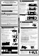

1. Determine hole positions according to left and righ t
side of the installation pla te. Th e hole cen ter is obtained
by measuring the distance as shown in the diagram above.
2. Dirll the piping plate hole with 65mm hole-core drill.
3. Drill the piping hole a t either the right or the left and the
hole should be slightly sla nted to the outdoor side.
4. Always take steps to prote ct the pipe when drilling metal
grid,metal plate or the like .
φ
INSTALLATION MANUAL FOR
ROOM AIR CONDITIONER
(Split Wall-Mounted Type)
DRILL A HOLE IN THE WALL
INSTALLATION PLATE MOUNTING
I
N
D
O
O
R
U
N
I
T
Please read these safety precauti onscarefully before installation
Be sure to fo llow a ll the preca utions below, they are all important for en surin g safety.
Th is s ymbol ind ica tes the po ssibility of death or serious in jury.
Th is s ymbol ind ica tes the po ssibility of i njury o r damage to property.
1) This equipment must be grounded and installed with ground leakage current breaker. It may cause
electrical shock if grounding is not perfect.
2) Do not install the unit at place where leakage of flammable gas may occur. In case gas leaks and
accumulates at surrounding of the unit, it may cause fire.
3) Carry out drainage piping as mentioned in installation instructions. If drainage is not perfect, water
may enter the room and damage the furniture.
1) Install according to this installation instructionsstrictly. If installation is defective, it will cause water
leakage, electrical shock,or fire.
2) Use the included accessories parts and s pecified parts for installation. otherwise, it will cause the set
to fall, water leakage, electrical shock fire.
3) Install at a s trong and firm locationw hich is able to withstand the set s weight. If the strength is not
enough or installation is not properly done, the set will drop and cause injury.
4) For electrical work, follow the local national wiring standard, regulati on and this installation instructions.
An independent circuit and single outlet must be used. If electrical circuit capacity is not enough or
defect found in electrical work, it will cause electrical shock fire.
5) Use the specified cable and connect tightly and clamp the cable so that no external force will be acted
on the terminal. If connection or fixing is not perfect, it will cause heat-up or fire at the connection.
6) Wiring routing must be properly arranged so that control board cover is fixed properly. If control board
cover is not fixed perfectly,it will overheat at connection point of terminal, fire or electrical shock.
7) When carrying out piping connection, take care not to let air substances other than the specified
refrigerant go into refrigeration cycle. Otherwise, it will cause lower capacity, abnormal high pressure
in the refrigeration cycle, explosion and injury.
8) Do not m odify the length of the power supply cord or use of extension cord, and do not share the
single outlet with other electrical appliances. Otherwise, it will cause fire or electrical shock.
SAFETY PRECAUTIONS
CAUTIO N
WARN ING
CAU TI ON
WAR NIN G
Please read this installation manual carefully before operating the unit to ensure correct installation.
If the power cord is damaged, replacement work shall be performed by authorised personnel only.
Installat ion must be performed in accordance with the requirement of NEC and CEC by authorized
personnel only.
Contact an authorized service technician for repair, maintenance and installation of this unit.
This appliance is not intended for use by persons(including children) with reduced physical, sensory
or mental capabilities, or lack of experience and knowledge, unless they have been given supervision
or instruction concerning use of the appliance by persons responsible for their safety.
Children should be supervised to ensure that they do not play with the appliance.
All the pictures in the instructions are for explanation purposes only. The actual shape should prevail.
The design and specifications are subject to change without prior notice for product improvement.
Consult with the sales agency or m anufacturer for details.
There should not be any heat source or stream
ne ar the unit.
There should not be any obstacles blocking the
air circ ulation.
A place where air circulation in the room is good.
A place where drainage can be easily done.
A place where noise prevention is tak en into
co nsideratio n.
Do not install the unit near the door w ay.
Ensure the spaces indicated by arrows from the
wall,ceiling,fence or other obstacles.
There should not be any direct sunlight. If unavoidable,
su nlight prevention should be taken into consid eration.
A( mm ) B( mm )
53 0 29 0
56 0 33 5
48 1
54 9
27 6
27 6
Mo unt i ng dime ns io ns
670x540x265
780x540x250
760x590x285
845x700x320
Indoor unit
Outdoor unit
If an awning is built over the unit to prevent
direct sunsi ght or rain,be careful that heat
ra diation from the con denser is n ot obstructed.
There should not be any animal or plant which
co uld be affected by hot air disch arged.
Keep the spaces indic ated by arrow from wall
ce iling, fence or other obstacles.
Do not place any obstacles which may cause
a short circuit of the di scha rged air.
Anchor the outdo or unit with a bolt and nut 10 or
8 tightly a nd horizontally on a concr ete or rigid mou nt.
φ
φ
Settlement of outd oor unit
NOTE: The outd oor unit you purchase may be like one
of the following. Install the outdoor unit according to the
dimen sion as indicated in the table below:
Air inle t
A ir outl et
Ai r i nl et
INSTALLATION PRECAUTIONS
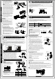
CONNECT THE CABLE TO THE IN DOOR UNIT
The cable size and t he current of th e fuse
or sw itch are d eterm ined by th e ma ximum
current in dicated on the name plate which
locat ed on the side pane l of the uni t.
Plea se refer to the n ameplate before
selec ting the c able, fuse and switch.
,
Terminal block of indoor unit
Connect th e cab le t o the indoor u nit
NOTE:
Before performing any electrical work, turn off the main power to the system.
1. Th e inside and outside connecting cable can be connected without removing the front grille.
2. Th e indoor power cord type is H05VV-F or H05V2V2-F, the outdoor power cord and
interconnected cord type is H07RN-F.
3. Lift the indoor unit panel up, remove the electrical box cover by loosening the screw.
4. Ensure the colour of wires of outdoor unit and the terminal Nos. are the same to the indoor s
respectively.
5. Wrap those cables not connected with terminals with insulation tapes, so that they will not touch
any electrica l components. Secure the cable onto the control board with the cord clamp.
NOTE:
Electronic box
cover
Front Pa nel
To outdoor unit
S
L2
L1
1
2
3
4
5
7
8
9
10
6
Installation Plate
Clip Anchor
Self-tapping Sc rew A ST3.9 x25
Seal(For cooling & heating models only)
Drain Joint(For cooling & heating models only)
Con nect ing
pip e
Assem bly
Liquid s ide
Ga s si de
Re mote controller
Air freshening filter(installed on Air filter)
Self-tapping Screw B ST2.9x10
Φ6.35
Φ9.52
Φ9.52
Φ12.7
Φ16
Parts you must purchase. Th e pip e
size differ from appliance to appliance.
Consult th e technician for the proper
size.
1
5-8 ( dep en di n g on mod els)
5 -8(de p en d i ng on mo d els )
1
1
1
2
1
1
Except the above parts provided,the other parts needed during installation you must
purchase.
Re mote controller hold er
ACCESSO RIES
Num ber
Name of Accessor ies
Q ty
opti o n al
part s
SELECT TH E BEST LOCATION
CONNECTIVE PIPE AND DRAINAGE INSTALLATION
1. Run the drain hose sloping down ward.
Do not install the drain hose as illustrated
in wrong figures.
2. When connecting extension drain hose,
insulate the connectin g part of extension
drain hose with a shield pipe, do not let
the drain h ose slack.
Dr a inage
Right
Wrong
Cor re ct orie nta tio n
of Inst al la tio n Plate
1. Fit the installation plate horizontally on
structural parts of the wall withspaces
around the in stallation plate.
2. If the wall is made of brick, concrete
or the like, drill five or eight 5mm
diamete r holes in the w all. Insert
clip anchor for appropriate m ounting
screws.
3. Fit the installation plate on the wall
with five or e ight t ype A screws.
Mount the Insta llation Plate and drill
holes in the wall according to the wall
structure and corresponding mounting
points on the installation plate. The
installation plate providedwith the
machine differ from appliance
to appliance.(Dimensions are in
mm unless otherwise stated)
NOTE:
NOTE:
"
"
Installation P late M ounting
The mounting wall is strong and sol id enough
to preven t it fro m th e vibration .
120mm or
more to wall
120mm or
more to wall
120mm or
more to wall
150m m or more to ceilin g
150mm or more to ceiling
Left r ear side
refrig erant
pipe ho le 65φ
835
140
110
Left r ear side
refrigerant
pipe hole 65φ
Right rear side
refrigerant
pipe hole 65φ
Right rear side
refrigerant
pipe hole 65φ
Indoor unit outline
Indoor unit outline
12 0mm o r
more to w all
120mm or
more to wall
Indoor unit outline
990
135
260
150mm or more to ceiling
Left rear side
refrigerant
pipe hole 65φ
Right rear side
refrigerant pipe
hole 65φ
Model C
Model D
Model B
Model A
120m m or
more to wall
750
180
110
Right rear sid e
refri gerant pipe
hole 65φ
Left rear side
refrigerant
pipe hole 65φ
1 50mm or more t o ceiling
Installation plate
Indoor unit outline
120m m or
more to wall
120mm or
more to wall
1186
21.5
275
275
590 3 3 3
90 0x 860x315
S ugge st Minimum W ire Size AWG : :( )America n Wire Gage
Appl iance Amps AWG Wire Size
10
13
18
25
18
16
14
12
30
10
Electric safety regulatio ns for the initial Insta llatio n
1. If ther e is serious safety problem about the power supply, the technicians should ref use to insta ll
the ai r conditioner and explain to the client until the problem is solved.
2. Power voltage should be in the r ange of 90 %~110%of rated voltage.
3. The surge prote ctor and main power switch with a 1.5 times ca pacity of Max. Current of the
unit s hould be installe d in power circuit.
4. Ensure the air c onditioner is grounde d well.
5. Accor ding to the attac hed E lectrical C onnection Diag ram located on the panel of the outdoor unit
to connect the wire.
6. All wiring m ust comply with local and natio nal electrical codes and be inst alled byqualified and
skilled elec tricians.
7.
8. An individu al branch circuit and single receptacle used on ly for this a ir conditio ner must b e
available. See the following table for suggested wire sizes and fuse specifications:
An all-pole disconnection device which has at least 3mm separation distance in all pole a nd a residual
current device(R CD) with t he rating o f not exce eding 30mA shall be incorporated in the fix ed wiring
according to the natio nal rule.
Electrical wor k