52Xi Industrial sewing machine Instruction manual Betriebsanleitung Postfach 17 03 51, D-33703 Bielefeld • Potsdamer Straße 190, D-33719 Bielefeld Telefon +49 (0) 521 / 9 25-00 • Telefax +49 (0) 521 / 9 25 24 35 • www.duerkopp-adler.com Ausgabe / Edition: 01/2010 Aenderungsindex Rev. index: 01.0 Printed in Czech Republic Teile-Nr./Part.-No.
All rights reserved. Property of Dürkopp Adler AG and copyrighted. Reproduction or publication of the content in any manner, even in extracts, without prior written permission of Dürkopp Adler AG, is prohibited. Alle Rechte vorbehalten. Eigentum der Dürkopp Adler AG und urheberrechtlich geschützt. Jede, auch auszugsweise Wiederverwendung dieser Inhalte ist ohne vorheriges schriftliches Einverständnis der Dürkopp Adler AG verboten.
Foreword This instruction manual is intended to help the user to become familiar with the machine and take advantage of its application possibilities in accordance with the recommendations. The instruction manual contains important information on how to operate the machine securely, properly and economically. Observation of the instructions eliminates danger, reduces costs for repair and down-times, and increases the reliability and life of the machine.
General safety instructions The non-observance of the following safety instructions can cause bodily injuries or damages to the machine. 1. The machine must only be commissioned in full knowledge of the instruction book and operated by persons with appropriate training. 2. Before putting into service also read the safety rules and instructions of the motor supplier. 3. The machine must be used only for the purpose intended. Use of the machine without the safety devices is not permitted.
Table of contents Page Introduction and safety instructions Part 1 - Instructions for use - 52Xi 1. Machine description . . . . . . . . . . . . . . . . . . . . . . . . . . . . . . . . . . . . . . . . . . . 5 2. Machine use . . . . . . . . . . . . . . . . . . . . . . . . . . . . . . . . . . . . . . . . . . . . . . . . . 5 3. Subclasses . . . . . . . . . . . . . . . . . . . . . . . . . . . . . . . . . . . . . . . . . . . . . . . . . 6 4. Sewing equipment . . . . . . . . . . . . . . . . . . . . .
For your notes:
1. Machine description · · · · · · · 2. A flatbed single-needle machine. It sews a double-thread zig-zag lockstitch. It has a bi-directional drop feed. The machine is equipped with a horizontal hook. Wick lubrication. There is an automatic bobbin winder on the machine arm. According to the selected class, the machine has a manual or automatic control by solenoid including thread trimming device.
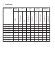
Subclasses 6 523i 447001 X X 524i 811001 X X 524i 847001 X X 525i 811001 X X 525i 847001 X X 527i 811001 X X 527i 847001 X X Thread Backtacking trimming (closing) X X X X X X X X X X X X X X X X X X X X with solenoid X with knee lever small (standard) X large 1 needle 523i 411001 Foot lifting with hand lever Hook with thread trimmer Needle number without thread trimmer Class and subclass with solenoid 3.
Sewing equipment 527 E 048 527i 811001; 527i 847001 Sewing equipment for two needle cordin seams with or without filler cord, 3-lined feed dog, needle size Nm 120-160, stitch length max. 5 mm, needle gauge 7 mm, for medium and heavy weight material.
Note: Sewing equipment is illustrated in the spare parts list. * Needles are not supplied.
5.
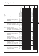
Cams for shape sewing for subclass 525i Commercial Order number Marking Quantity sewing points/ 1 cam turn Quantity sewing points/pattern Pattern width Single-needle Double-needle 525 Z 037 S080 674219 12 525 Z 038 S080 674113 12 525 Z 039 S080 674114 525 Z 040 525 525 - 4400 3800 4 1-3 4,5 - 10 3800 3400 12 12 1-3 4,5 - 10 3800 3400 S080 674115 12 6 1,5-3 3,5 - 6 3800 3400 Z 041 S080 674116 12 12 1,5-5 4,5 - 10 3800 3800 Z 042 S080 674117 12 3 1,5-4 3,5 - 6
6.
7. 7.1 Machine operation Needle threading A A B C Attention! Danger of injury! Thread when the main switch is switched off and motor stopped! – – 12 Do the threading according to picture (A) and detail (B). When trimming the material edges, do the threading according to picture (A) and detail(C).
7.2 Hook thread winding A A 3 1 5 GB 4 2 B 3 2 – – – – – – – Fix the bobbin (1) on the winder. Do the threading according to picture (A), wind 5 times round the bobbin. Insert the thread under cutter (2) and tear off by pulling in the arrow direction (3). Pull the lever (4) in the arrow direction (5). Start the machine up. After the bobbin winding, wind the thread round the cutter (2) according to picture (B) and tear it off by pulling in the arrow direction (3).
7.3 Bobbin fixing and hook threading 8 6 5 2 3 4 2 1 2 7 Attention! Danger of injury! Switch the main switch off and wait for the motor stopping. – – – – – 14 Tilt the flap (1), grip it and pull the bobbin case (2) out of the hook. Put the bobbin (3) in the bobbin case with the thread end (4) oriented according to the picture (2). Draw the thread end (4) through the slit (5), pull under the spring (6) and pull into the slit (7).
7.4 7.4.1 Thread tension adjustment Needle thread tension adjustment 1 2 Secondary tensioner adjustment (1) – Adjust the secondary tensioner (1) so that it has as small tension as possible, but high enough so as the thread cannot be pulled out from the tensioner (1) at the material removing after previous trimming (when the tensioner (2) is opened - switched off). (The tensioner (1) is never switched off).
7.4.2 Hook thread tension adjustment 7 3 2 7 A B 8 4 6 1 5 C Attention! Danger of injury! Do adjustments when the main switch is switched off and motor stopped! – The hook thread tension depends on the adjustment of springs (1) and (2). Tension spring (1) adjustment – Remove the bobbin case (3) from the machine and insert a full-wound bobbin (4). – Do a complete threading according to picture (B).
7.5 Needle replacement 1 3 2 D Attention! Danger of injury! Do the needle replacement when the main switch is switched off and motor stopped. – – – GB Loosen the screw (1) and remove the needle (2). Fix a new needle and turn it so that the needle scarf (3) is oriented according to detail (D). Tighten the screw (1).
7.6 Foot lifting 1 2 3 Foot lifting with a hand lever – Lift the foot by pressing the lever (1) to a stop (foot remains lifted). – Lower the foot by returning the lever (1) to initial position or by pressing the knee lever (2) /if there is any/ and by its subsequent releasing or by the automatic foot lifting by means of the pedal and subsequent pedal releasing. – After the foot lifting by hand lever, the machine may be started up (e. g. when winding the hook thread).
7.7 Foot pressure setting 1 – – – Regulate the foot pressure by means of a screwdriver (1) which is supplied with the machine accessories. The pressure increases by turning in the arrow direction and vice versa. The foot pressure should be as small as possible, but strong enough so that the feeding is reliable even at a high sewing speed. – 7.8 Stitch length setting 3 2 1 – Turn the knob (1) so that the number (2) indicating the required stitch length in mm is opposite the screw (3).
7.9 Backtacking (reverse feed; closing up) 2 1 Backtacking with a hand lever(applies to manually controlled subclasses) – Press the lever (1) downwards. The machine will feed in the reverse direction until you release the lever. Backtacking with a microswitch (applies to automatically controlled subclasses) – Press the microswitch (2). The machine will backtack until you release the grip.
7.10 Setting of zig-zag stitch width (throw) and position C 3 2 1 A GB Attention! At setting the zig-zag stitch width (throw) and position the needle must not be inside the sewn material. There is a threat of the needle breaking! Setting of zig-zag stitch width – Press the lever (1) in the arrow direction (A) until it strikes the lever (2) - the lever arrest is released (2).
7.11 Starting up of manually controlled machine with clutch motor 2 1 3 – – – – 22 Start up the motor (1) with the switch (2) - the drive motor is running continuously. Tread the pedal (3). The drive friction clutch switches in this way and the sewing machine starts running. Regulate the sewing speed by pressure on the pedal (3). The friction clutch slip changes and thus also the machine speed changes in dependency on the pressure. Release the pedal(3). The sewing machine will stop.
7.12 Control of machine equipped with positioning motor and solenoid automatic control 7.12.1 Control pedal -2 -1 0 1 2 13 The pedal position is scanned with a proximity switch which distinguishes 16 levels.
7.12.2 Key control panel 2 1 Key 24 Function 1 Hand backtacking When the key is pressed at sewing, the sewn material is fed backwards.
8. Efka DC1550/DA321G positioning motor GB DA321G control contains all needed control elements for a function switchover and parameter setting.The operation is possible without the control panel, the sewing programming is not enabled. To the machine control also control panels V810 and V820 can be connected which are available as an attachment. By means of V820 control panel it is possible to program the sewing.
9. 9.1 Sewing with machine equipped with positioning motor Machine automatic functions The machine has functions stated below which are automatically carried out during the seam sewing dependent on: – pre-selection – pedal position (according to the machine operator s selection) – work phase of seam sewing Automatic function Pre-selection Needle positioning • needle down at machine seam-stop • needle up at machine seam-stop Note: After the seam finishing* the machine always stops with the needle up.
The automatic function pre-selections are described in the drive manufacturer s accompanying Instruction for Use. For Efka DA321G motor also see the drive manufacturer s Instruction for Use on website www.efka.net. Certain automatic functions can be pre-selected by means of keys. Their description is included in the publication Efka Instructions for Use, sections 4, 12, 13. Further automatic functions can be pre-selected through the drive parameter change. Every such function has its parameter number.
10. Maintenace 10.1 Cleaning and checking Attention! Danger of injury! Maintenance may be carried out only when the machine is switched off and the motor stopped! Attention! Maintenance must be carried out in prescribed intervals. Neglection of maintenance may result in malfunction requiring costly repair. 3 1 5 Mainenance operation 2 4 Maintenance interval Throat plate (1) disassembly. Cleaning of throat plate, hook(2), feed dog (3) and their surroundings.
10.2 Lubrication Attention! Danger of injury! Oil may cause dermatic diseases. Avoid complexion staining with oil. In case of staining wash the affected spot in water with soap. Attention! Handling of mineral oils is subject of legal prescriptions. Deposit the debased oil in an authorized dangerous waste scrap-yard! Protect the environment. Prevent oil leakages.
1 2 6 3 4 7 8 5 9 Oil lubrication – If the oil volume in the tank (1) drops to the level indicated with MIN mark,add oil through the hole (2) up to MAX mark. – Add oil into tank (3) through the hole (4) at least once a week until the oil starts flowing from the terminal(5). – Add several drops of oil in holes (6) and (7) once a month. Grease lubrication – Add grease in grease cups(8) and (9) by means of a lubrication press once a year.