Publication Part No. SK-2373-R CAUTION This manual contains important information for the correct installation, operation and maintenance of the equipment described herein. All persons involved in such installation, operation, and maintenance should be thoroughly familiar with the contents. To safeguard against the possibility of personal injury or property damage, follow the recommendations and instructions of this manual and keep it for further reference.
Contents Section I 1-1. 1-2. 1-3. 1-4. Table 3. Table 4. 1-5. 1-6. Section II 2-1. 2-2. 2-3. 2-4. Table 2-1. Figure 2-2. 2-5. 2-6. 2-7. Figure 2-3. Section III 3-1. 3-2. Figure 3-1. 2 General Information ................................................................................................................. 3 General...................................................................................................................................... 3 Applications .................................
Section I General Information 1-1. General This manual contains maintenance instructions for Duff-Norton® rotating ball screw actuators. It describes and details procedures for installation, disassembly, cleaning, inspection, and assembly of these actuators. 1-2.
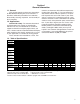
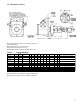
1-4. Dimensions Note: Ball nut must be kept from rotating to prevent it from self-lowering. Worm and gear set is not self-locking. Use brake on worm shaft or motor. Housing dimensions and base configurations vary. Table 3. Model Number UM-28632 UM-9803 & KUM-2803 UM-98031* KUM-28031* UM98004 & KUM-28004 UM-9806 UM-98061* UM-9811 UM-98111* AUM-9821 UM-9826 UM-2861* Upright Models Rating 1/2 TON 2 TON 2 TON Drawing Ref.
1-4. Dimensions (cont.) Note: Ball nut must be kept from rotating to prevent it from self-lowering. Worm and gear set is not self-locking. Use brake on worm shaft or motor. Housing dimensions and base configurations vary. Table 4. Model Number DM-28632 DM-9803 & KDM-2803 DM-98031* KDM-28031* DM98004 & KDM-28004 DM-9806 DM-98061* DM-9811 DM-98111* ADM-9821 DM-9826 DM-2861* Inverted Models Rating 1/2 TON 2 TON 2 TON 3 TON 5 TON 5 TON 10 TON 10 TON 20 TON 25 TON 50 TON Drawing Ref.
1-5. Important Precautions In order to ensure that actuators provide good service over a period of years, the following precautions should be taken: 1. Select an actuator that has a rated capacity greater than the maximum load that may be imposed on it. 7. The ball screw and lifting nut should be checked periodically for excessive backlash and spalling of race ways. 8. The lubrication procedures for normal and severe service conditions, as described in Section II, paragraph 2-1, should be closely followed.
2-1. Lubrication Section II Maintenance Unless otherwise specified, actuators are shipped packed with grease which should be sufficient for one month of normal operation. For normal operation the actuator should be lubricated once a month, using Extreme Pressure grease Shell Oil Co. Shell Albida LC EP #2 (Shell Product Code 70311). This grease has been thoroughly evaluated in Duff-Norton actuators and has demonstrated superior lubricating properties affecting both wear life and maximum duty cycle.
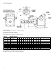
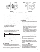
long enough to extend 1 1/2˝ to 2˝ beyond each end of the lifting nut. Note Apply tape to arbor O.D. at end away from ball screw pilot to prevent lifting nut from accidentally running off of arbor during disassembly (an O-ring with a large cross section, stretched over the arbor, is ideal for this purpose.) Table 2-1. Dimensions Ball Nut Storage Arbor Actuator Model No. 28632 Ball Screw Root Dia. (in) .480 Arbor O.D. (in) .500 9803 2803 .820 .889 98031 28031 .820 .889 .870 1.140 1.140 1.140 1.
Figure 2-2. Ball Nut Storage Arbor 16. Remove key (22) from ball screw (5). 17. Remove spacer (23) from ball screw. Note On some models spacer is threaded. Note Some models do not have a spacer. 18. Inverted Models - Remove guide bushing (16) from shell (3). 19. For units with an expansion plug (4a) in shell (3) or shell cap (2), damaged plugs must be removed. Drive or press plug out of shell or shell cap with a large diameter punch (1˝). Disassembly is now complete. 2-5. Cleaning 1.
away from ball screw threads. 6. Thread locknut (20) on ball screw (5) and tighten securely against worm gear (6). Make certain that this assembly is tightly drawn up. Note On some locknuts the tapped set screw hole is not centered. In this case assemble the locknut with the tapped hole farthest away from the worm gear face. 7. Install set screw (21) in locknut (20) locking the nut in place (some models do not utilize a set screw).
20. Refer to Figure 2-2 for reassembly of lifting nut (24) from tube arbor to ball screw (5). a. With lifting nut centered on arbor tube, grasp lifting nut and arbor to prevent lifting nut from running off of arbor, and remove binding wire. b. Position arbor over ball screw (5) pilot. Note Flange of lifting nut should face toward actuator shell and away from ball screw pilot. c. Gently slide lifting nut (24) down arbor and thread it onto ball screw (5).
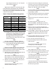
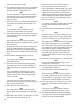
Section III Illustrated Parts List 3-1. General This section contains an exploded illustration of the 2800 and 9800 Series rotating ball screw actuators. The number adjacent to each part on the illustration is the index number. Keyed to this index number on the parts list is the part name 3-2. Parts List for 2800 and 9800 Series Rotating Ball Screw Actuators Index No.
A Figure 3-1.
® P.O. Box 7010 Charlotte, NC 28241-7010 General Office (704) 588-0510 Customer Service (800) 477-5002 Customer Service (704) 588-4610 FAX (704) 588-1994 Email: duffnorton@cmworks.com © 2000 Yale Industrial Products, Inc. www.duffnorton.