
User guide

3
Section I
General Information
1-1. General
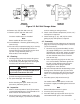
This manual contains maintenance instructions
for Duff-Norton® rotating ball screw actuators. It
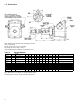
describes and details procedures for installation,
disassembly, cleaning, inspection, and assembly of
these actuators.
1-2. Applications
Industrial Use Only The actuators described
and illustrated in this manual are intended for
industrial use only and should not be used to lift,
support or otherwise transport people unless you
have a written statement from Duff-Norton Company
which authorizes the specific actuator unit, as used
in your application, as suitable for moving people.
These actuators are intended for a clean, non-
corrosive environment with ambient temperatures
ranging from -20 to 200 ° F. If your environment is
dirty and/or contains abrasive particles it is impor-
tant to protect the screw with a boot. If your atmo-
sphere is corrosive it is important to specify a non-
corrosive material or finish. Duff-Norton can provide
stainless steel, nickel plated or epoxy coated actua-
tors. If your duty is high or your use severe, more
frequent lubrication should be employed. Duff-
Norton publishes a Mechanical Actuator Design
Guide, Catalog No. 2003, which you may find
helpful in the selection and application of mechani-
cal actuators. If you need additional help, please
contact Duff-Norton at (800) 477-5002.
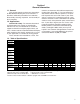
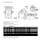
1-3. Table of Specifications
Note: Hold back torque is restraining torque at the worm shaft, to keep load from running down.
*Dimensionally same as Model 2803 † Dimensionally same as Model 9806
‡ Dimensionally same as Model 9811 ** 9803 Base is 4 1/8˝ x 6˝
∆ Prefix for these model numbers is KUM for upright units and KDM for inverted units.
Standard Actuator Upright UM28632 KUM2803/UM9803 KUM28004/UM98004 KUM2804/UM9804 UM9806 UM98061 UM9811 UM98111 AUM9821 UM9826 UM2861
Model Numbers Inverted DM28632 KDM28031/UM98031 KDM28004/UM98004 KDM2804/DM98004 DM9806 DM98061 DM9811 DM98111 ADM9821 DM9826 DM2861
Special Actuator Upright UM38632 UM3803/UM9803 UM38004/UM98004 UM3804/UM108004 UM10806 UM10806 UM10811 UM10811 UM10821 UM10826 UM3861
Model Numbers Inverted DM32632 DM3803/UM9803 DM38004/UM98004 DM3804/DM108004 DM10806 DM10806 DM10811 DM10811 DM10821 DM10826 DM3861
Capacity, Tons 1/2 2 2 3 5 5 10 10 20 25 50
Diameter of 5/8 111 11/64 1 1/2 1 1/2 1 1/2 1 1/2 2 1/4 3 4
Lifting Screw (inches) .200 Lead .250 Lead 1.000 Lead .413 Lead .474 Lead 1.000 Lead .474 Lead 1.000 Lead .500 Lead .660 Lead 1.000 Lead
Base Size (inches) 2 1/4 x 4 3 1/2 x 7** 3 1/2 x 7 3 1/2 x 7 6 x 8 6 x 8 7 1/2 x 8 3/4 7 1/2 x 8 3/4 8 1/4 x 11 10 1/4 x 13 3/4 9 3/4 x 19 3/4
Std Ratio 5:1 6:1 6:1 6:1 6:1 6:1 8:1 8:1 8:1 10 2/3:1 10 2/3:1
Worm Gear Ratios Optional 20:1 12:1 24:1 12:1 24:1 24:1 24:1 24:1 24:1 32:1 32:1
Optional — 24:1 — 24:1 — — — — — — —
Std Ratio 25 24 6 14.526 12.667 6 16.888 8 16 16.16 10.66
Turns of Worm Optional 100 48 24 29.052 50.667 24 50.667 24 48 48.48 32
For 1˝ Raise Optional —96—58.104 — — — — — — —
Std Ratio 1/3 2 2 2 4 4 5 5 5 8 15
Maximum H.P. Optional 1/6 3/4 1/2 3/4 3/4 3/4 1 1/2 1 1/2 1 1/2 2 1/2 6
Per Actuator Optional — 1/2 — 1/2 — — — — — — —
Starting Torque Std Ratio 10.5 50 180 110 220 500 350 800 700 925 2,700
at Full Load Optional 5.0 30 80 68 90 206 175 400 325 475 1,500
(lb-ins) Optional —25 — 50———————
Running Torque Std Ratio 9.5 45 160 100 180 410 300 700 650 825 2,200
at Full Load Optional 4.5 25 70 60 80 183 150 290 300 425 1,200
(lb-ins) Optional —20 — 45———————
Std Ratio 65 59 59 59 70 70 65 65 61 60 55
Actuator Efficiency Optional 38 44 33 44 39 39 42 42 44 39 33
Rating (%) Optional —33 — 33———————
Weight with Base
Raise of 6˝ (lbs)
2.75 20 20 21 40 40 50 50 115 235 520
Weight for Each
Additional 1˝ of
Raise (lbs)
0.10 0.3 0.3 0.4 0.9 0.9 0.9 0.9 1.5 2.9 5.0
Hold-Back Torque Std Ratio 12 2 7881111 24 24 92
at Rated Load Optional 0.5 1 0.5 2 0.5 0.5 0.5 0.5 2 2 33
(lb-ft) Optional — 0.5 — 0.5 — — — — — — —