
Manual

2
Section I
General Information
1-1. General
This manual contains maintenance instructions
for Duff Norton translating machine screw actuators
of two ton to 75 ton capacity. It describes and details
procedures for installation, disassembly, cleaning,
inspection, and assembly of these actuators.
1-2. Applications
Industrial Use Only The actuators described
and illustrated in this manual are intended for
industrial use only and should not be used to lift,
support or otherwise transport people unless you
have a written statement from Duff-Norton which
authorizes the specific actuator unit, as used in your
application, as suitable for moving people.
These actuators are intended for a clean, non-
corrosive environment with ambient temperatures
ranging from -20 to 200 ° F. If your environment is
dirty and/or contains abrasive particles it is impor-
tant to protect the screw with a boot. If your atmo-
sphere is corrosive it is important to specify a non-
corrosive material or finish. Duff-Norton can provide
stainless steel, nickel plated or epoxy coated actua-
tors. If your duty is high or your use severe, more
frequent lubrication should be employed. Duff-
Norton publishes a Mechanical Actuator Design
Guide, Catalog No. 2003, which you may find helpful
in the selection and application of mechanical
actuators. If you need additional help, please con-
tact Duff-Norton at (800) 477-5002.
* For loads from 25% to 100% of actuator load rating. Torque requirements are approximately proportional to the load.
** Closed heights are for standard upright top plate models and may vary with different screw end, inverted models, or when bellows boot is used.
Contents
Section I General Information................................................................................................................................................ 2
1-1. General .................................................................................................................................................................... 2
1-2. Applications ............................................................................................................................................................ 2
1-3. Specifications .......................................................................................................................................................... 2
1-4 Important Precautions ............................................................................................................................................. 3
1-5. Warranty and Warranty Repair ............................................................................................................................... 4
Section II Maintenance ............................................................................................................................................................ 4
2-1. Lubrication .............................................................................................................................................................. 4
2-2. Rebuild Procedure .................................................................................................................................................. 4
2-3 Required Tools ........................................................................................................................................................ 4
2-4. Disassembly ............................................................................................................................................................ 4
2-5. Cleaning .................................................................................................................................................................. 5
2-6. Inspection ................................................................................................................................................................ 5
2-7. Assembly ................................................................................................................................................................ 5
2-8. Anti-Backlash Nut Function ................................................................................................................................... 6
2-9. Anti-Backlash Nut Adjustment ............................................................................................................................... 6
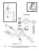
Section III Illustrated Parts List ................................................................................................................................................ 6
3-1. General ................................................................................................................................................................... 6
3-2. Parts List ................................................................................................................................................................. 6
Figure 3-1. Exploded Illustration .............................................................................................................................................. 7
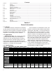
1-3. Specifications
Table 1. 1800 (2000) and 9000 (10000) Series
Standard Actuator Upright 1802 & 9002 9005 9010 9015 9020 9025 9035 1850 & 9050 9075
Model No. Inverted 1801 & 9001 9004 9009 9014 9019 9024 9034 1849 & 9049 9074
Special Actuator Upright 2002 & 1000
2
10005 10010 10015 10020 10025 10035 2050 & 1005
0
10075
Model No. Inverted 2001 & 10001 10004 10009 10014 10019 10024 10034 2049 & 1004
9
10074
Rated Load (tons) 251015 20 25 35 50 75
Diameter of 11 1/222 1/4 2 1/2 3 3 3/4 4 1/2 5
Lifting Screw (inches) .250 Pitch .375 Pitch .500 Pitch .500 Pitch .500 Pitch .666 Pitch .666 Pitch .666 Pitch .666 Pitch
Acme Acme Acme Acme Acme Acme Acme Square Square
Closed Height** (inches) 5 1/4 7 7 1/4 8 9 1/4 11 12 13 16 1/2
Base Size (inches)
3 1/2 x 7
4 1/8 x 6 1/4
6 x 87 1/2 x 8 3/4 7 3/4 x 9 1/4 8 1/4 x 11
10 1/4 x
13 3/4
10 1/4 x
15 1/2
9 3/4 x 19 3/4
10 1/2 x 21 3/4
14 x 23
Worm Gear Ratios Std Ratio 6:1 6:1 8:1 8:1 8:1 10 2/3:1 10 2/3:1 10 2/3:1 10 2/3:1
Optional 24:1 24:1 24:1 24:1 24:1 32:1 32:1 32:1 32:1
Turns of Worm Std Ratio 24 16 16 16 16 16 16 16 16
For 1˝ Raise Optional 96 64 48 48 48 48 48 48 48
Maximum H.P. Std Ratio 24555881515
Per Actuator Optional 1/2 3/4 1 1/2 1 1/2 1 1/2 2 1/2 2 1/2 6 6
Torque at Std Ratio 120 450 750 1,430 2,050 2,700 4,000 7,500 12,000
Full Load* (in-lbs) Optional 50 185 400 820 1,170 1,200 2,400 4,200 6,600
Actuator Efficiency Std Ratio 23.2 22.1 23.7 20.2 18.8 18.7 15.8 13.8 12.4
Rating (%) Optional 13.3 12.1 15.1 12.9 12.0 10.5 8.9 8.3 7.5
Weight with Base
Raise of 6˝ (lbs)
17 35 52 66 93 160 240 410 650
Weight for Each
Additional 1˝ of
Raise (lbs)
.33 .85 1.4 1.5 2.6 2.5 3.7 5.5 6.5