Publication Part No. SK-2463-22 Translating Tube Actuators Model Numbers M-2464 & M-2465 Rotating Screw Actuators Model Numbers M-2462 & M-2463 CAUTION This manual contains important information for the correct installation, operation and maintenance of the equipment described herein. All persons involved in such installation, operation, and maintenance should be thoroughly familiar with the contents.
Contents Section I Section II Section III Section IV Section V Section VI 2 Introduction ................................................................................................................. 3 1-1. General ............................................................................................................... 3 1-2. Intended Use ....................................................................................................... 3 1-3. Safety Considerations ......................
Section I Introduction 1-1. General This manual provides instructions for the installation, operation, and maintenance of the Duff-Norton® Modular Actuator. It includes proper procedures for the disassembly, cleaning, inspection, rebuilding, lubrication, and assembly of the actuator. To ensure efficient and long, satisfactory use of this unit, read and understand the information herein, and follow the instructions closely. 1-2.
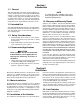
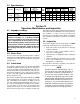
Section III Dimensions and Specifications 3-1. Dimensions - Rotating Screw Actuators (Models M-2462 and M-2463) Warning Use only replacement parts supplied by or approved by Duff-Norton. Nonauthorized parts may be inadequate, resulting in serious injury or death in event of failure. 3-2.
3-3. Specifications Model No. M-2462 M-2464 M-2463 M-2465 Screw Dia. .875 Dia. Acme .25 Pitch R.H. Double 1.0 Dia. Acme .25 Pitch R.H.
Section V Disassembly and Assembly 5-1. Lubricant When rebuilding this actuator, use only Albida LC EP#2 grease from Shell Oil Company. 5-2. Required Tools A bearing puller and press, a soft jaw table clamp, and common hand tools are required for proper disassembly and assembly of the actuator. 5-3. General Procedures Duff-Norton recommends following these procedures during disassembly and assembly of the actuator: 1. Tag critical parts to facilitate reassembly. 2.
NOTE For assembly procedures for Translating Tube actuators, see Paragraph 5-7. NOTE Be sure all parts are clean and dry before assembling the actuator. 1. Assemble one load bearing cup (13) into the shell (9), and the other load bearing cup into the shell cap (19). 2. Assemble one worm bearing (2) into the motor mounting flange end of the shell (9) (see NOTE below). NOTE The bearing must be installed from the opposite end of the shell. 3.
5-6. Disassembly - Translating Tube Actuators (Models M-2464 and M-2465) Disassemble the Duff-Norton® Translating Tube Modular Actuator as follows, referring to Figure 6-2 on page 12. Read the instructions thoroughly before disassembling the actuator. of the worm shaft. The worm bearing (2) next to the retaining ring (1) groove in the shell (9) will be driven out by the worm. The other worm bearing (2) should remain in the shell until the load bearing cup (13) has been removed. 12.
2. Assemble one worm bearing (2) into the motor mounting flange end of the shell (9) (see NOTE below). NOTE The bearing must be installed from the opposite end of the shell. 3. Notice that one end of the worm (4) has a hole in the center of the shaft, and one end does not. Press the remaining worm bearing (2) on to the end of the shaft WITH the hole. 4. Assemble the worm (4) into the shell (9) and worm bearing (2), and then install the retaining ring (1) in the shell. 5.
This completes the assembly procedures for actuators not equipped with limit switches. When assembling an actuator equipped with limit switches, continue with the instructions below. 27. Apply two or three drops of Loc-Tite No. 35 Extra Strength Retaining Ring Compound to the shell bore. If a new (replacement) limit switch adapter is being installed, follow steps 28 and 29 below. If a used (previously spot drilled) adapter is being installed, proceed directly to step 30. 28.
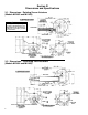
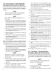
6-2. Parts List for Rotating Screw Actuators Index No. Figure 6-1 1 2 3 4 5** 6 7 8 9 10 11 12 13 Part Name Qty Req. Retaining Ring 1 Worm Bearing 2 Spring Pin (Worm) 1 Worm 5:1 Ratio 1 20:1 Ratio 1 Flexible Coupling 1 Key 1 Pipe Plug 1 Grease Fitting 1 Shell 1 Set Screw 2 Decal 1 Lock Nut 1 Load Bearing 2 * This No. is equal to travel plus 1.
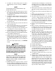
6-3. Parts List for Translating Tube Actuators (Models M-2464 and M-2465) Index No. Figure 6-2 1 2 3 4 5** 6 7 8 9 10 11 12 13 14 15 Part Name Qty Req. Retaining Ring 1 Worm Bearing 2 Spring Pin (Worm) 1 Worm 5:1 Ratio 1 20:1 Ratio 1 Flexible Coupling 1 Key 1 Pipe Plug 1 Grease Fitting 1 Shell 1 2 Set Screw 1 Decal Lock Nut 1 Load Bearing 2 Worm Gear 5:1 Ratio 1 20:1 Ratio 1 Spacer 1 * This No. is equal to travel.
Notes 13
P.O. Box 7010 Charlotte, NC 28241-7010 Customer Service (800) 477-5002 FAX (704) 588-1994 Email: duffnorton@cmworks.com www.duffnorton.com © 2000 Yale Industrial Products, Inc.