
User`s manual


Section 4 – Press Options
Dukane Part No. 403–556–03
Page 35
4. Connect the cable to the DPC connector J-401 (Thruster Stroke
Encoder).
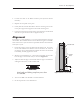
5. Replace the rear panel on the press.
6. Gently slide the encoder head down until the mounting screw holes
in the press support base appear in the head’s mounting slots.
7. Center the screw holes in the mounting slots. Secure the encoder head
with the two pan-screws but do not tighten them yet.
Alignment
The purpose of this alignment is to set the internal reference mark for
the encoder. This reference mark resets the distance register in the DPC
after each thruster cycle and ensures repeatable distance measurements
from cycle to cycle.
1. Check the position of the encoder scale’s mounting hole slots using
the 6" ruler. Measure the distance from the center of the screw to
the edge of the slot in both directions. When the screws are centered
horizontally, carefully tighten the screws.
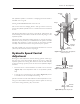
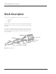
2. Measure a vertical distance of 1.375 inches (34.92 mm) up from the
bottom edge of the encoder scale, as shown in Figure 4-6.
3. Adjust the bottom edge of the encoder head to align to this distance
and tighten the screws on the encoder head.
WARNING
Keep hands and clothing away from press when
it is activated.
4. Turn on the DPC. Set the DPC to measure distance.
5. Set the air pressure to the desired level.
Encoder Scale
Encoder
Head
1.375”
Figure 4-6 Distance Encoder Alignment