DUKANE CORPORATION SEACOM DIVISION TECHNICAL MANUAL UNDERWATER ACOUSTIC BEACON MODELS DK100/DK120/DK130/DK140 April 13, 2004 REV 13 DUKANE CORPORATION ST. CHARLES, ILLINOIS 60174 PHONE: 630-762-4050 FAX: 630-762-4049 DOCUMENT NO. 03-TM-0037 © DUKANE CORPORATION E-MAIL: seacom@dukcorp.com INTERNET: www.dukcorp.
This manual should be read in its entirety prior to any installation, operation, testing or maintenance of the DK100/DK120/DK130/DK140 Underwater Acoustic Beacons.
TABLE OF CONTENTS SECTION I ................................................................................................................... 5 GENERAL INFORMATION ..................................................................................... 5 1.1. INTRODUCTION. .......................................................................................................... 5 1.2. GENERAL DESCRIPTION. ..........................................................................................
6.6. BATTERY REPLACEMENT AND TESTING. ............................................................. 18 6.7. BEACON OFF-CURRENT TEST. ............................................................................... 21 6.8. BATTERY DISPOSAL. ............................................................................................... 21 6.9. BEACON STORAGE. ................................................................................................. 21 6.10. BEACON OVERHAUL...............................
SECTION I GENERAL INFORMATION 1.1. INTRODUCTION. 1.1.1. GENERAL. This manual contains the description, theory, installation and maintenance for the DK100/DK120/DK130/DK140 Underwater Acoustic Beacon, hereafter referred to as the “DK Series”, manufactured by Dukane Corporation, Seacom Division, 2900 Dukane Drive, St. Charles, Illinois, 60174. See Figures 1 and 2. These beacons have been tested to, and meet, or exceed, all requirements of FAA TSO-C121. shock and deep-water immersion.
DK100/DK120 BEACON SPECIFICATIONS Operating Freuency............................................... 37.5 kHz ± 1 kHz Operating Depth.................................................... Surface to 20,000 feet (6096 meters) Pulse Length......................................................... 10 milliseconds + 10% Pulse Repetition Rate............................................ Not less than 0.9 Pulse/Sec Operating Life.......................................................
DK130/DK140 BEACON SPECIFICATIONS Operating Freuency............................................... 37.5 kHz ± 1 kHz Operating Depth.................................................... Surface to 20,000 feet (6096 meters) Pulse Length......................................................... 10 milliseconds + 10% Pulse Repetition Rate............................................ Not less than 0.9 Pulse/Sec Operating Life.......................................................
SECTION II INSTALLATION 2.1. GENERAL. This section describes the installation of the beacon mounting kits and the installation of the DK Series beacons into these mounts. 2.2. INSTALLATION CRITERIA OF THE BEACON. NOTE All installations to Cockpit Voice Recorders and Flight Data Recorders should be in accordance with the recorder manufacturer’s approved procedures and hardware. 2.3. SURVIVABILITY. 2.3.1.
2.6. INSTALLATION PROCEDURES FOR THE DK100/DK120 AND THE N30A26 SERIES MOUNTING KIT. 2.6.1. GENERAL. Model N30A26 Series Mounting Kit (Cradle Type) is an aluminum extrusion with a screw-attached securing plate that provides rugged mounting and protection of the beacon within the aircraft. See Figure 3. The beacon should be mounted horizontally with the switch end forward, if possible.
C. Test the beacon as outlined in Section IV to insure operation prior to installation. 2.7.2. MOUNTING PROCEDURE A. Lay out four holes as shown in Figure 5. Position mounting kit carefully to avoid interference with other structures. Observe the clearances required as shown in Figures 5 and 6, and in established tool and maintenance clearances. B. Drill the four 0.272 inch (0.691 cm) (“I” drill) holes in the mounting surface as shown in Figure 5. Figure 4.
If vertical mounting is employed, the switch end should be facing downwards to reduce the accumulation of dirt, grease, and water on the switch end. Rotate the beacon in the mount, so that the markings and beacon replacement date label can be read. Figure 8. Securing Beacon in N30A21A Mounting Kit 2.7.3. INSTALLING BEACON INTO N30A21A MOUNTING KIT. Figure 6. N30A21A Mounting Kit and Beacon Overall Dimensions F. Install a flat washer and nut on each end of the retainer straps. A.
2.8. INSTALLATION PROCEDURES FOR THE DK130/DK140 AND THE N30A29 SERIES MOUNTING KIT. 2.8.1. GENERAL. Model N30A29 Series Mounting Kit (Cradle Type) is an aluminum extrusion with a screw-attached securing plate that provides rugged mounting and protection of the beacon within the aircraft. See Figure 9. The beacon should be mounted horizontally with the switch end forward, if possible.
B. Make sure that the beacon case and water switch, are free of grease or film. If in doubt, wipe clean with mild detergent C. Test the beacon as outlined in Section IV to insure operation prior to installation. 2.9.2. MOUNTING PROCEDURE. A. Lay out four holes as shown in Figure 11. Position mounting kit carefully to avoid interferencewith other structures. Observe the clearances required as shown in Figures 11 and 12, and in established tool and maintenance clearances. B. Drill the four 0.272 inch (0.
E. Insert the ends of the retainer straps through the 0.272 inch (0.691 cm) holes in the mounting surface. When horizontal mounting is used, position beacon with switch end forward. If vertical mounting is employed, the switch end should be facing downwards to reduce the accumulation of grease and dirt on the switch end. Rotate the beacon in the mount, so that the markings and beacon replacement date label can be read. F. Install a flat washer and nut on each end of the retainer straps. Figure 14.
SECTION III OPERATION 3.1. THEORY OF OPERATION. 3.1.1. The DK Series beacon is a battery-operated underwater acoustic pulse generator that is activated when the water switch is immersed in either fresh or salt water. 3.1.2. The water switch is part of a triggering circuit, which when actuated will initiate normal pulsing of the beacon circuit. The signal is coupled to a piezo-ceramic transducer ring.
SECTION IV TESTING 4.1. GENERAL. The DK Series beacon should be tested before and after installation in the mounting kit and at recommended maintenance intervals. See Sections V and VI. CODE MINIMUM ACCEPTABLE VOLTAGE A 3.55 VOLTS B 2.97 VOLTS C 2.97 VOLTS D 2.97 VOLTS 4.2. BATTERY TESTING. Use a high impedance voltmeter (input impedance of 10 M ohms) (not required when using TS100 or TS200 Test Set) to perform the following procedure: Figure 17. Beacon Voltage Code A.
SECTION V MAINTENANCE DK100/DK130 5.1. GENERAL. This section contains DK100/DK130 Beacon cleaning, beacon testing, battery testing, disposal and storage procedures. Initially beacons must be tested at every installation or beacon change. The required schedule for battery replacement, available only at Dukane Corporation is every six years.
SECTION VI MAINTENANCE DK120/DK140 6.1. GENERAL. This section contains DK120/DK140 Beacon cleaning, beacon testing, battery replacement and testing, disposal and storage procedures. Initially beacons must be tested at every installation or battery change. The required schedule for Battery Replacement and Off-Current Testing is every six years. 6.4.2. Any situation that could possibly crush or penetrate the case of the beacon should be avoided. 6.5. BEACON DISASSEMBLY.
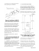
G. Clean the threads, O-ring groove in the body and the threads on the cover by wiping them thoroughly with solvent. CAUTION FOREIGN SUBSTANCES IN LUBRICANT ON SEALING SURFACES MAY DAMAGE THREADS AND/OR ALLOW WATER LEAKAGE THROUGH THE O-RING SEAL. SCRATCHES OR GOUGES ON SEALING SURFACES WILL ALSO CAUSE WATER LEAKAGE. Figure 18. Battery End Cover Removal With Vise Clamp and Spanner Wrench 6.6.2. BATTERY REPLACEMENT. A.
Figure 20. Beacon Exploded View Showing Relative Location of Battery and Related Parts WARNING J. Perform OFF-CURRENT TEST as outlined in Section 6.7. REPLACE BATTERY WITH AUTHORIZED REPLACEMENT PARTS ONLY. USE OF AN UNAUTHORIZED BATTERY WILL VOID THE WARRANTY AND MAY CAUSE AN INOPERATIVE OR DANGEROUS CONDITION. USE OF AN UNAUTHORIZED BATTERY MAY PRESENT A RISK OF FIRE OR EXPLOSION. SEE FIGURE 19 PAGE 18 FOR REPLACEMENT BATTERY KIT. K.
WARNING DO NOT RECHARGE, DISASSEMBLE, HEAT ABOVE 160°F (71°C) OR INCINERATE. THERE IS A RISK OF BATTERY FIRE, EXPLOSION, AND BURNS. 6.8. BATTERY DISPOSAL. Figure 21. RBB Label Placement Dispose of battery in accordance with all local, state and federal regulations. Dispose of batteries promptly, keep away from children. 6.7. BEACON OFF-CURRENT TEST. 6.9. BEACON STORAGE. Connect test leads as shown in Figure 22 and check for current leakage between battery and beacon body.
SECTION VII WARRANTY DK100/DK120/DK130/DK140 The Dukane Corporation warrants that the electronics and case of the Model DK100/DK120DK130/ DK140 Underwater Acoustic Beacon (hereafter referred to as the “unit”) will be free from defects in materials and workmanship for six years from the date of shipment from Dukane Corporation. Dukane Corporation will remanufacture or replace any unit or battery found not to be in conformity with this warranty.
SECTION VIII SERVICE PROGRAM DK100/DK120/DK130/DK140 8.1. BEACON RETURN – DEFECTIVE. 8.1.1. In the case of a failure which is determined to be within the Warranty terms (Section VII), the beacon will be replaced by Dukane Corporation at the sole discretion of Dukane Corporation. 8.1.2. When a beacon is returned to the customer after warranty service, the remainder of the original warranty will be applied to the returned beacon. 8.2. BEACON RETURN - NO DEFECT.
SECTION IX PROCEDURE FOR RETURNING DK SERIES BEACON TO FACTORY 9.1. BEACON SERVICE. 9.1.4. SHIPPING INSTRUCTIONS. When the beacon is returned under warranty, ship to: 9.1.1. PACKAGING. Insure that proper protection for the beacon is provided i.e. protection from inadvertent shorting of the water switch and protection from surface scratches or abrasions. 9.1.2. INFORMATION TO BE INCLUDED WITH THE BEACON. A. Reason for the return. B. Serial Number of the beacon(s). C. Return Authorization Number (See 9.1.3.
03-TM-0037 REV 13 Page 25 of 24