
Instruction Manual


Page 25
Section 4 – Controls and Connections
Dukane Manual Part No. 403-583-00
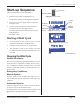
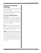
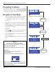
Start-up Sequence
After all connections have been completed.
1. Push the Power Switch to ON (Figure 4-2).
The generator performs a self-diagnostics sequence.
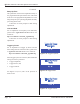
2. Two Power-up screens appear briey - Figure 4-3,
and Figure 4-3A.
3. The next screen is an Operate screen ready for a
new weld to be done. The display shows:
The setup used for the last weld, and zeros for any
weld parameters.
See Figure 4-3B.
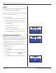
Figure 4-2 Power Switch
Push OFF
Push ON
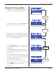
Starting a Weld Cycle
1. If the generator is not powered, press its Power
Switch/Circuit Breaker to the ON position.
2. Select the setup you want to use, if appropriate.
3. The generator is ready to start a weld cycle when
the Ultrasound Activate/Cycle Start Input (Pin 12) is
activated.
Stopping the Weld Cycle
Normal Conditions
The cycle stops when the programmed welding cycle ends
if the generator is congured to weld by time or energy.
If it is congured to weld by automation, the cycle ends
when the Ultrasound Activate/Cycle Start Input (Pin 12)
is deactivated.
Emergency Conditions
Manual System
Push the Power Switch to OFF (See Figure 4-2.) to
stop the ultrasound signal. This may be done under any
conditions.
Automated System
Customer-supplied external controls provide the means
to stop the cycle for an automated system.
An auxiliary cable connects these external controls to the
iQ generator at the INPUTS/OUTPUTS connector.
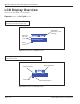
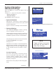
Figure 4-3B Operate Screen, After Power-up
Weld by Time
Weld Time 0.000 S
Weld Energy 0 J
# 1
DUKANE
Setup #1
xxxxxxxxx
xxxxxx
http://www.dukane.com
iQ AL Series xxkHz
Figure 4-3 Power-up Screen 1
Software
version
Current
Setup
Website
Address
MB FPGA
version
Figure 4-3A Power-up Screen 2
U.S. Patent #7475801
Trigger by Power
available