
Power Supply User Manual


Page 16
iQ Series, Ultrasonic Power Supply AL User’s Manual
Dukane Manual Part No. 403-583-00
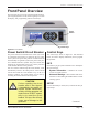
Connecting Cables - Quick
Start Guide
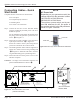
Complete the basic connections as shown below:
• AC Line Input
• I/O (Input/Output) Connector
• Grounding Stud
• AC Power Cord Connection
Step 1. Connect the AC line. For the 100/120V model,
plug the permanently attached power cord into a
suitable receptacle.
For the 200/240V model, attach the female end of
the power cord to the generator’s power inlet con-
nector - A in Figure 3-3.
Step 2. Attach the I/O cable connector to the generator’s
input/output connection. - B in Figure 3-3.
Secure the connector to the system using the two
jack screws attached to the connector hood.
Step 3. Ground the generator chassis with the supplied 14-
Gauge wire. Attach one end to the grounding stud
- C in Figure 3-2. Attach the other end to the near-
est grounded metal pipe or equal earth ground.
Step 4. Attach the male end of the power cord to a suit-
able line receptacle.
Connector - See Page 19 for information about the rear
panel CONFIGURATION connector E.
NOTE
AC Power Inlet
Depending on your generator model, line
voltage required for the generator is either
100-120 VAC at 50/60 Hertz or
200-240 VAC at 50/60 Hertz.
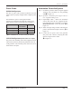
The unit has a power switch, and is pow-
ered ON whenever the AC line power is
live and the switch is in the ON position as
shown in Figure 3-4 below.
Figure 3-3 Generator Detail - Rear View
(100/120 Volt Model)
Figure 3-4 Rocker-style Power Switch/Circuit Breaker
Push ON
Push OFF
U.S. PATENT 5,880,580
OTHER PATENTS PENDING
POWER LINE OUTLET
MUST BE GROUNDED.
DISCONNECT LINE POWER
BEFORE REMOVING COVER.
ST. CHARLES IL 60174
MADE IN U.S.A.
DUKANE CORP
-WARNING-
INPUTS / OUTPUTS
CONFIGURATION
PE
U/S
IEC Connector Detail
200/240V Model
PE
C
A
B
Power Cord with Strain Relief
E
D