
Instruction Manual


Page 17
Section 3 – Installation
Dukane Manual Part No. 403-573-02
Connecting Cables
Standard Model Conguration
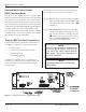
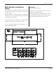
Complete three basic connections for the standard con-
guration as shown below:
• AC Line Input
• System Control Inputs/Status Outputs
• Ultrasound Output
• Grounding
Details about the various system connectors and their pin
assignments are covered in the next section.
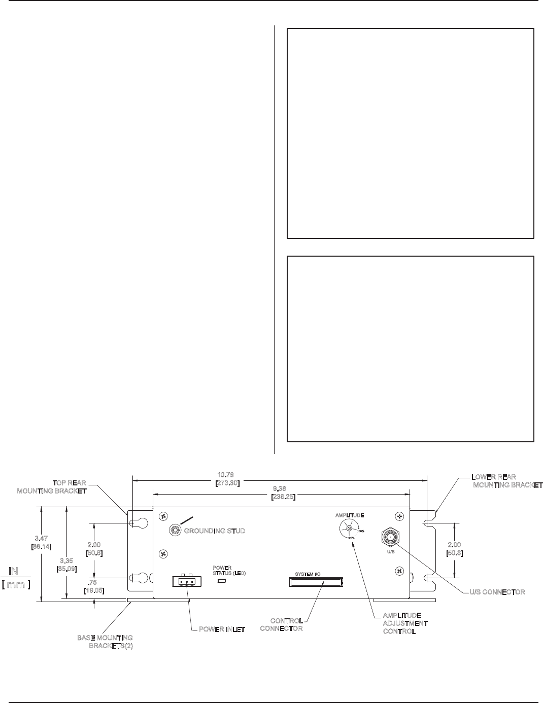
Step 1. Wire the AC line connector, and attach it to the
generator’s power inlet connector, matching the
power source line, ground, and neutral with the
generator’s line, ground, and neutral connector
pins - A in Figure 3–1. (See Figure 2-1 also.)
Step 2. Wire the user-supplied automation system control
inputs/status outputs to the CONTROL CON-
NECTOR, and attach it to the system I/O port -
B in Figure 3-1.
Step 3. Attach a high–voltage coaxial ultrasound cable
(from the ultrasonic probe) to J1, the ultrasound
output connector - C in Figure 3-1.
Step 4. Connect the included ground wire from the ground-
ing stud, D in Figure 3-1, to earth ground.
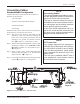
Figure 3-1 Generator Front View - Standard Model
NOTE
AC Power Inlet
Line voltage required for the generator is
200-240 VAC at 50/60 Hertz and 6.3 Amps,
or 100-120VAC at 50/60 Hz and 15 Amps.
The unit does not include a power switch,
and is powered ON whenever the AC line
power is live.
The unit can be switched ON/OFF with a
user-supplied AC circuit breaker wired to
the AC power inlet connection.
NOTE
Connecting Cables
Two-piece pluggable terminal block connec-
tors are used for the System I/O connections
and the AC Power Inlet connections.
This type of connector allows the wiring to
be attached to the screw terminal connec-
tor, which plugs into the mating connector
on the iQ Auto system front panel.
In the event a eld replacement unit is re-
quired, the screw terminal connectors with
the wires can be easily detached and then
plugged into the replacement unit.
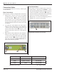
LOWER REAR
MOUNTING BRACKET
BASE MOUNTING
BRACKETS(2)
2.00
[50.8]
2.00
[50.8]
.75
[19.05]
3.35
[85.09]
3.47
[88.14]
9.38
[238.25]
POWER INLET
CONTROL
CONNECTOR
U/S CONNECTOR
U/S
SYSTEM I/O
POWER
STATUS (LED)
10.76
[273.30]
IN
[ mm ]
TOP REAR
MOUNTING BRACKET
GROUNDING STUD
AMPLITUDE
20%
100%
AMPLITUDE
ADJUSTMENT
CONTROL
See NOTE on
Page 22.