
Instruction Manual


Page 18
iQ Series, Auto User’s Manual
Dukane Manual Part No. 403-573-02
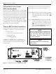
Pin Signal Name
1 Enable Out (+22V Current Limited)
2 Enable In (Jumper to Pin1, without an E-Stop switch)
3 Overload Out (system overload status output)
4 U/S Status Out
5 Any Fault Out
6 Power OK Out
7 Output Common (chassis ground - non-isolated)
8 Spare Status Out (programmable status output)
9 Analog Power Out + (1mV = 1 Watt)
10 Analog Power Out - (analog monitor signal common, non-isolated)
11 Fault Reset Input
12 U/S Active Input
13 Input Common (electrically isolated from chassis ground)
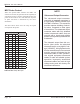
Table 3-I System I/O Connector Signals
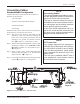
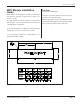
System I/O Connector Pinout
The SYSTEM I/O connector is a two-piece pluggable
terminal block connector.
Table 3-I lists the signal names and descriptions, with
more detailed descriptions listed on the next page.