
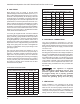
Specifications
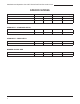


7
Installation and Operation of 613 & E Series Gas Fired Convection Oven
your oven. To keep your warranty in force, a proper
ventilation system must be employed, either direct
vented or under a canopy.
The best way to vent your oven is by placing it under a
properly designed mechanically driven exhaust hood.
The hood should be sized so the equipment that it is
designed to ventilate ts underneath with a minimum six
(6) inch (152 mm) overhang on all sides not adjacent to
a wall. The distance from the oor to the lower edge of
the canopy should not exceed seven (7) feet (2.2 m).
The hood should have adequate capacity and provide
a sufcient supply of make- up air. Ventilation hoods
come in many sizes and capacities. Hood capacity is
expressed in cubic feet per minute (CFM). The total
make-up and exhaust air required for the canopy hood
should be about 22 CFM per oven section. Information
for the proper construction and installation of ventilating
hoods may be obtained from the “Standard for the
Installation of Equipment for the Removal of Smoke
and Grease-Laden Vapors from Commercial Cooking
Equipment, NFPA-96”.
Occasionally it is not possible or practical to install a
powered canopy hood. In those cases the oven can
be vented directly by means of a direct ue method.
Correctly venting your oven is very important to insure
proper cooking results and preclude any premature
failures in the burner or burner compartment. The
direct ue method incorporates a drafthood that is
mounted to the top of the oven (or the upper oven
section in a stacked unit). The ue then rises from the
drafthood vertically to a point 6-8 feet above the roof
or any close structure. The ue is then capped with an
approved vent cap to isolate the ue from the external
environmental conditions.
The direct ue method does not incorporate the ability
to replace air consumed by and vented from the oven.
An adequate supply of room make-up air must be
provided if your oven is to be vented by this method.
The total makeup air requirement for one oven section
is approximately 30 CFM.
• Turn Gas Shut Off to ON Position
• Turn Power Switch to COOK Position
• Set Thermostat to Desired Temperature
• Turn Power Switch to OFF Position
• Wait 5 Minutes Before Relighting Oven
Before assembling and installing the oven, please
check to make sure that all necessary parts are
present. In addition to the oven itself, there will also be
legs, feet or casters, the ue/vent guard or drafthood
and drafthood collar assembly, (for double sections,
retaining clips, ue riser and/or common manifold) and
miscellaneous hardware. Please check the interior of
all oven sections for the parts needed to assemble
and install your oven(s).
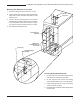
• Once the oven has been removed from the carton,
lay it on its left side (the side without the controls),
hold the leg and align with the threaded holes in
the front comer of the bottom of the oven. Carefully
start the threads of the comer leg bolt (5/16"-18 X
1/2"), avoid cross threading.
• Align the leg plate holes in each leg with those in
the corners of the oven bottom and secure using
two 5/ 16"-18 x 1/2" bolts. Tighten all bolts rmly.
Repeat this procedure for all legs.
• Raise the oven up on its legs.
Level the oven by turning the adjustable feet in or
out as needed.
• Casters are available as an option for both the
single and double oven sections.
• The installation of casters requires the removal of
the adjustable feet from the legs. This is done by
placing the bit of a large screwdriver against the lip
of the foot and rapping the screwdriver to drive the
foot out of the leg. The caster is then inserted fully
into the opening where the foot came out and the
locking nut tightened to expand the compression
sleeve of the caster.