
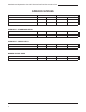
Specifications
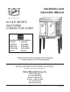


Installation and Operation of 613 & E Series Gas Fired Convection Oven
8
The casters with locking brakes are best
mounted on the front side of the oven for easier
access.
If you plan to use casters and exible fuel gas
connectors, a xed restraint of the proper length must
be incorporated to secure the oven to a non-movable
surface to eliminate strain on the connector. If the oven
is removed from its normal position, the restraint must
then be reattached when returned.
• Ovens ordered for installation under a powered
canopy exhaust hood should have the ue guard
in place. This item can be installed by placing it
over the ue opening, making sure that it does
not obstruct the ue, and attaching it with the
screws provided.
• Ovens ordered for installation in a location other
than under a powered canopy exhaust hood are
supplied with a drafthood & drafthood collar. This
device mounts to the top of the upper oven section
by attaching the drafthood adapter to the ue
opening with the screws provided, the drafthood is
then mounted on top of the adapter. The ue pipe
is attached vertically to the drafthood.
Each oven section and all its component parts have
been tested thoroughly and inspected before your oven
was shipped from the factory. However, it is sometimes
necessary to further test or adjust the oven once it has
been installed. Such adjustments are the responsibility
of the Dealer or Installer. These types of adjustments
are not considered defects, rather a normal and routine
part of the proper installation of the equipment.
These adjustments include but are not limited to:
• Adjustments and recalibration of the thermostat
• Adjustment to the doors
• Burner or pilot adjustment.
• Adjustments to the gas pressure regulator.
• Leveling, and tightening of fasteners.
No installation should be considered complete without
proper inspection and, if necessary, any adjustments
by qualied service or installation personnel.
It is also important not to obstruct the natural ow of
combustion and ventilation air if the oven is to operate
properly. This oven should not be installed on a curb
base or sealed to the wall. Either condition can restrict
the ow of air to the combustion compartment or prevent
proper ventilation of the blower motor. The blower motor
has a thermal protection device that will trip because
of excessive ambient temperature at the back of the
oven. This condition should be corrected immediately
to avoid damaging the oven permanently.
Before making any connections to the oven, check
the ratings plate to be sure the oven specications
concur with the type of gas and voltage to be supplied
to the oven.
The rating plate is located behind the lowered lower
front panel. To access, loosen the four screws below
the doors, and pull panel outward.
The plate bearing the oven's serial number is
attached to the underside of the upper ledge above
the control panel.
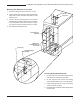
• Secure the short legs to the bottom of the lower
section as described in previous section.
• Casters are installed by the method described for
single section ovens. Previous section.
• Place upper section on top of lower section and
align all edges of the ovens.
• Locate securing clips and align with holes on rear
frames of oven section, install three screws each
as provided and tighten.
• At the rear of the oven, install the ue connector
by sliding it up through the ue vent opening in
the top of the oven and over the upper ue vent.
Push it ush with the back of the oven then slide it
down over the lower ue vent. Attach with screws
provided.
• Install ue guard or drafthood adapter, drafthood
and drafthood collar to upper section.