
Use and Care Manual

dIXEL
Operating Manual
1592020160
1592020160 XR06CX GB r1.2 07.11.07.doc XR06CX 2/3
8. PARAMETERS
REGULATION
Hy Differential: (0,1°C ÷ 25°C / 1°F ÷ 45°F) Intervention differential for set point. Compressor Cut
IN is SET POINT + differential (Hy). Compressor Cut OUT is when the temperature reaches the
set point.
LS Minimum SET POINT: (-55°C÷SET/-67°F÷SET): Sets the minimum value for the set point..
US Maximum SET POINT: (SET÷99°C/ SET÷99°F). Set the maximum value for set point.
ot First probe calibration: (-9.9÷9.9°C / -17°F ÷ 17°F) allows to adjust possible offset of the first
probe.
P2 Evaporator probe presence: n= not present; y= the defrost stops by temperature.
oE Second probe calibration: (-9.9÷9.9°C / -17°F ÷ 17°F) allows to adjust possible offset of the
second probe.
od Outputs activation delay at start up: (0÷99min) This function is enabled at the initial start up of
the instrument and inhibits any output activation for the period of time set in the parameter.
AC Anti-short cycle delay: (0÷50 min) minimum interval between the compressor stop and the
following restart.
Cy Compressor ON time with faulty probe: (0÷99 min) time during which the compressor is active
in case of faulty thermostat probe. With Cy=0 compressor is always OFF.
Cn Compressor OFF time with faulty probe: (0÷99 min) time during which the compressor is OFF
in case of faulty thermostat probe. With Cn=0 compressor is always active.
DISPLAY
CF Measurement unit: (°C÷°F) °C =Celsius; °F =Fahrenheit. WARNING: When the measurement
unit is changed the SET point and the values of the parameters Hy, LS, US, oE, o1, AU, AL
have to be checked and modified if necessary.
rE Resolution (only for °C):(dE ÷ in) dE= decimal between -9.9 and 9.9°C; in= integer
Ld Default display: (P1 ÷ P2) P1= thermostat probe; P2= evaporator probe. SP=Set point (only
XR04CX)
dy Display delay: (0÷15 min.) when the temperature increases, the display is updated of 1 °C/1°F
after this time.
DEFROST
td Defrost type: (EL – in) EL= electrical heater, compressor OFF; in= hot gas, compressor ON;
dE Defrost termination temperature: (-55÷50°C / -67÷99°F) if P2=Y it sets the temperature
measured by the evaporator probe, which causes the end of defrost.
id Interval between defrost cycles: (0÷99 minutes) Determines the time interval between the
beginning of two defrost cycles.
Md Maximum length for defrost: (0÷99 min. with 0 no defrost) when P2=n, (not evaporator probe:
timed defrost) it sets the defrost duration, when P2 = y (defrost end based on temperature) it sets
the maximum length for defrost.
dd Start defrost delay: ( 0÷99min) This is useful when different defrost start times are necessary to
avoid overloading the plant.
dF Display during defrost: (rt / it / SP / dF) rt= real temperature; it= start defrost temperature; SP=
SET-POINT; dF= label dF.
dt Drip time: (0÷99 min) time interval between reaching defrost termination temperature and the
restoring of the control’s normal operation. This time allows the evaporator to eliminate water
drops that might have formed due to defrost.
dP Defrost at power –on: (y÷n) y= at power on defrost starts; n= defrost doesn’t start at power-on
FANS
FC Fans operating mode: (cn, on, cY, oY) cn= in runs with the compressor, OFF during defrost;
on= continuous mode, OFF during defrost;; cY= runs with the compressor, ON during defrost;
oY= continuous mode, ON during defrost.
Fd Fans delay after defrost: (0÷99 min) Interval between end of defrost and evaporator fans start.
FS Fans stop temperature: (-55÷50°C / -67°F ÷ 99°F) setting of temperature, detected by
evaporator probe, above which fans are always OFF.
ALARMS
AU Maximum temperature alarm: (AL÷99°C/99°F) when this temperature is reached the alarm is
enabled, after the “Ad” delay time.
AL Minimum temperature alarm: (-55÷AU°C /-67÷AU°F) when this temperature is reached the
alarm is enabled, after the “Ad” delay time.
Ad Temperature alarm delay: (0÷99 min) time interval between the detection of an alarm condition
and alarm signalling.
dA Exclusion of temperature alarm at startup: (0÷99 min) time interval between the detection of
the temperature alarm condition after instrument power on and alarm signalling.
DIGITAL INPUT
iP Digital input polarity: (oP ÷ cL) oP= activated by closing the contact; cL= activated by opening
the contact;
iF Digital input configuration: (EA/bA/do/dF/Au/Hc) EA= external alarm: “EA” message is
displayed; bA= serious alarm “CA” message is displayed; do= door switch function; dF= defrost
activation; Au =not used; Hc= inversion of the kind of action;
di Digital input delay: (0÷99 min) with iF=EA or bA delay between the detection of the external
alarm condition and its signalling. . With iF=do it represents the delay to activate the door open
alarm.
dC Compressor and fan status when open door: (no/Fn/cP/Fc): no= normal; Fn = Fans OFF; cP
=Compressor OFF; Fc = Compressor and fans OFF;
rd Regulation with door open: (n÷y) n = no regulation if door is opened; Y= when di is elapsed
regulation restarts even if door open alarm is present;
OTHER
d1 Thermostat probe display (read only)
d2 Evaporator probe display (read only)
Pt Parameter code table
rL Software release
9. DIGITAL INPUTS (ONLY XR03CX)
The free voltage digital input is programmable in different configurations by the “i1F” parameter.
DOOR SWITCH (iF=do)
It signals the door status and the corresponding relay output status through the “dC” parameter: no =
normal (any change); Fn = Fan OFF; CP = Compressor OFF; FC = Compressor and fan OFF.
Since the door is opened, after the delay time set through parameter “di”, the door alarm is enabled,
the display shows the message “dA” and the regulation restarts if rd = y. The alarm stops as soon
as the external digital input is disabled again. With the door open, the high and low temperature alarms
are disabled.
EXTERNAL ALARM (iF=EA)
As soon as the digital input is activated the unit will wait for “di” time delay before signalling the “EA”
alarm message. The outputs status don’t change. The alarm stops just after the digital input is de-
activated.
SERIOUS ALARM (iF=bA)
When the digital input is activated, the unit will wait for “di” delay before signalling the “CA” alarm
message. The relay outputs are switched OFF. The alarm will stop as soon as the digital input is de-
activated.
START DEFROST (iF=dF)
It starts a defrost if there are the right conditions. After the defrost is finished, the normal regulation will
restart only if the digital input is disabled otherwise the instrument will wait until the “Md” safety time is
expired.
INVERSION OF THE KIND OF ACTION: HEATING - COOLING (iF=Hc)
This function allows to invert the regulation of the controller: from cooling to heating and viceversa.
10. INSTALLATION AND MOUNTING
Instrument XR06CX shall be mounted on vertical panel, in a
29x71 mm hole, and fixed using the special bracket supplied.
The temperature range allowed for correct operation is 0÷60 °C.
Avoid places subject to strong vibrations, corrosive gases,
excessive dirt or humidity. The same recommendations apply to
probes. Let air circulate by the cooling holes.
11. ELECTRICAL CONNECTIONS
The instrument is provided with screw terminal block to connect cables with a cross section up to 2,5
mm
2
. Before connecting cables make sure the power supply complies with the instrument’s
requirements. Separate the probe cables from the power supply cables, from the outputs and the
power connections. Do not exceed the maximum current allowed on each relay, in case of heavier
loads use a suitable external relay.
11.1 PROBES
The probes shall be mounted with the bulb upwards to prevent damages due to casual liquid
infiltration. It is recommended to place the thermostat probe away from air streams to correctly
measure the average room temperature. Place the defrost termination probe among the evaporator
fins in the coldest place, where most ice is formed, far from heaters or from the warmest place during
defrost, to prevent premature defrost termination.
12. HOW TO USE THE HOT KEY
12.1 HOW TO PROGRAM THE HOT KEY FROM THE INSTRUMENT (UPLOAD)
1. Program one controller with the front keypad.
2. When the controller is ON, insert the “Hot key” and push
key; the "uP" message appears
followed a by flashing “Ed”
3. Push “SET” key and the “Ed” will stop flashing.
4. Turn OFF the instrument remove the “Hot Key”, then turn it ON again.
NOTE: the “Er” message is displayed for failed programming. In this case push again o key if you want
to restart the upload again or remove the “Hot key” to abort the operation.
12.2 HOW TO PROGRAM AN INSTRUMENT USING HOT KEY (DOWNLOAD)
1. Turn OFF the instrument.
2. Insert a programmed “Hot Key” into the 5 PIN receptacle and then turn the Controller ON.
3. Automatically the parameter list of the “Hot Key” is downloaded into the Controller memory, the
“do” message is blinking followed a by flashing “Ed”.
4. After 10 seconds the instrument will restart working with the new parameters.
5. Remove the “Hot Key”..
NOTE: the “Er” message is displayed for failed programming. In this case push again o key if you want
to restart the upload again or remove the “Hot key” to abort the operation.
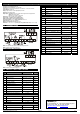
13. ALARM SIGNALLING
Mess. Cause Outputs
"P1" Room probe failure Compressor output according to “Cy” e “Cn”
"P2" Evaporator probe failure Defrost end is timed
"HA" Maximum temperature alarm Outputs unchanged
"LA" Minimum temperature alarm Outputs unchanged
“EA” External alarm Outputs unchanged
“CA” Serious external alarm All outputs OFF
“dA” Door Open Compressor and fans restarts
13.1 ALARM RECOVERY
Probe alarms P1” and “P2” start some seconds after the fault in the related probe; they automatically
stop some seconds after the probe restarts normal operation. Check connections before replacing the
probe. Temperature alarms “HA” and “LA” automatically stop as soon as the temperature returns to
normal values.
Alarms “EA” and “CA” (with iF=bL) recover as soon as the digital input is disabled.
14. TECHNICAL DATA
Housing: self extinguishing ABS.
Case: frontal 32x74 mm; depth 60mm;