Du Mont 3 DU MONT TYPE 180 Twenty-two Tube, AC, Superheterodyne, Television Receiver GENERAL FEATURES No expense has been spared in the production of these receivers and every up-to-date television and radio development has been incorporated. These receivers are classed as "Electrostatic and Direct Vision.
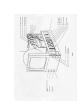
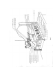
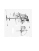
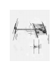
Du Mont 4 CIRCUIT ARRANGEMENT A simple straight line layout is used in these receivers that should prove extremely helpful to the serviceman. Viewed from the front, the video receiver is on the left side of the chassis and the sound receiver is on the right. Fig. No. 1 shows the front controls and the sound receiver while Fig. No. 2 shows the rear adjustments and the video receiver. The top portion of the chassis contains both sweep circuits along with the modulating circuit of the cathode-ray tube.
Du Mont 7 INSTALLATION OF RECEIVER Antenna Installation Location of the Antenna In the installation of television receivers the proper antenna is a necessity. Successful installations will result from attention to details, while slipshod and careless work will bring only poor customer satisfaction and repeat calls. There is nothing difficult about the installation of television aerials, a little patience and experience is all that is required.
Du Mont Directional Effects In the simple Dipole, directional effects are not very pronounced, but it does have a rather sharp no-signal radius and it is possible in some instances to materially reduce interference by placing the offending source in this area. If the installation of the receiver is being made at quite a distance from the transmitter or if the signal level is very low due to local conditions it is well to consider the use of a reflector.
Du Mont 4. Astigmatic Positioning Control This is adjusted in conjunction with Control No. 5 to give the best possible focus on the corners of the picture. 5. Horizontal Positioning Control This control positions the picture horizontally. 6. Horizontal Size Control The width of the picture is adjusted by this control. 7.
Du Mont 12 In Fig. 6 the use of a copper oxide rectifier and neon lamp can be explained as follows. The D.C. component necessary for background level, is introduced by the action of the copper oxide (Westector) V24. The neon lamp V23 is provided to protect the rectifier from high voltage surges when the equipment is first turned on. Assuming that the controls are properly FAULT No picture. set and handled, the first step will be to determine the location of the trouble and isolate the defective portion.
Du Mont While no fast rule can be laid down, once the section failing has been decided on it will generally be found that a systematic check correctly interpreted will locate the fault. A voltage check of the suspected circuit along with the checking of the tubes employed will probably be the next step. Then, if the voltages are correct and cathoderay oscillograph is available it can be used to trace the source of the trouble.
Du Mont 14 Equipment (Laboratory) In addition to the equipment recommended for the field group the following items are suggested. Du Mont Type 202 Phasmajector Television Signal Generator. Du Mont Type 204A Low Frequency Square Wave Generator. Du Mont Type 204B High Frequency Square Wave Generator. Du Mont Type 207 Modulated High Frequency Oscillator. Du Mont Type 205 Oscillograph. Laboratory Type Signal Generator.
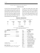
Du Mont 20 RESISTOR VALUES R – Regular S – Special W - Wire R. Ohms Watt Class R. Ohms Watt Class 49 50 51 52 53 54 55 56 57 58 59 60 61 62 63 64 65 66 67 68 69 70 71 72 73 74 75 76 77 78 79 80 81 82 83 84 87 88 89 90 94 95 96 97 99 100 10,000 10 meg 6,000 1 meg 200,000 80,000 100,000 100,000 500,000 15,000 6,000 50,000 25 meg 1.5 meg 1.
Du Mont 21 CONDENSER VALUES C. Mfd. 69 70 71 72 73 74 75 76 77 78 79 80 81 82 83 84 85 86 87 89 90 91 93 95 96 97 98 99 100 104 105 106 110 200 201 202 203 204 205 206 207 208 209 210 211 212 213 .1 .05 .000075 .0025 .0025 .005 25. .04 .0005 .25 .01 .04 .1 .25 .1 .1 .05 .0005 16. 8. 8. 16. 16. 4. 4. .2 .2 .2 .2 .0003 .02 25. .0002 3-30 mmf. 3-30 mmf. 3-30 mmf. 3-30 mmf. 3-5 .0006 .0006 .0006 .01 3-30 mmf. .0006 .01 .01 .
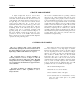
Du Mont 22 ' TERMINAL VOLTAGES Using Weston Model 772 20,000 Ohms per Voltmeter (with Televerter) Grid Screen (Control) 150 -4.3 l55 -4.3 -----2.3 290 -11.5 Cathode to ground --------190 -2.0 Contrast on full 190 -3.5 180 -2.25 170 -2.25 185 -2.0 Cannot be measured at the grid of V6. Should read –4 volts at center tap of 5Z3 high voltage winding to ground. 225 -7.
Du Mont 23 DOUBLE IMAGE Where two images appear separately on the screen, one of the sweep circuits is adjusted to half its correct speed. If the horizonta1 is at fault the images will appear side by side, conversely if the images are vertically displaced the vertical sweep is at fault FIELD In the RMA Television System there are two fields to each frame. In other words each picture is comprised of two fields scanning alternate lines.