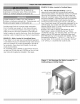
SERIES Hodels 3EW,65 3EW,75 3EWI,O0 4EW,90 4EW1,25 4EW1,50 SEW1,20 5EW1,75 OIL-FIRED CAST IRON HOT WATER INSTALLATION, OPERATION & HAINTENANCE HANUAL ,?__,_g_,',,_& _!._,_,, , _',!_,._;_#_ _i:_' _,_;_! _._,_.',_rL_ ....................................................... :::::::::::::::::::::::::::::: ............. , .......................................... dS H Maximum Allowable Working Pressure 50 psi. Manufactured ECR by: international, inc. 220! DwyerAwnue.
Safety Notices Boiler Ratings Fresh Air System Chimney And 3 Operating Boiler The Checking Oil Boiler Electrical Equipment ......................... ....................................... Boiler ................................. Controls Instructions Cleaning Hints .................. .................... ..................................... Boiler installation 18 20 23 25 26 27 .........................................
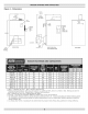
Figure 1 = Dimensions 17 1/2" RIELLO 2&5000 -13 3/4' TEMR/ BECKETT PRESSUiqE OR CARLiN GAUGE "_'_ I / LIMIT CONTROL RELIEF VALVE 1 1/4" OUTLET_ _,#,,#ATER OUTLET "_)PTIONA LOW LIMIT I_/CO L I"ANKLESS COIL NTROL WAT£R (With Tank_ess HEATER WITH 1/2" NPT CONNE£T_ONS CoiU} 36.01 iO0 O&BURNER /_' DRAIN FRONT VIEW VALVE RIGHT SIDE VIEW WITH SWING DOOR I 1/4 '_ (Furnished) REIURN N_PP_ E & BACKVIEW REDUCING >>3EW.65 80 70 86,3 8" X 8" X 15" >>3EW.
This boiler has been designed for residential installations. Tf used for commercial applications, all jurisdictional requirements must be met. This may require wiring and/or piping modifications. Manufacturer is not responsible for any changes to the original design. 1, Read the Owner's Manual for Safe Operation. Failure to follow rules for safe operation and instructions can cause malfunction of boiler and result in death, serious bodily injury, and/or property damage.
iiiiiiiiiiiiii iiiiiiiiiiiiiiiiiiiiiiiiiiiiiiiiiiiiiiiiiiiiiiiiiiiiiiiiiiiiiiiiiiiiiiiiiii iiiiiiiiiiiiiiii iiiiiiiiiiiiiiii iiiiiiiiiiiiiiiiiiiiiiiiiiiiiiiiiiiiiiLi :i!6!i_ i_i_! !_iii!_!!i !!i!! i!! i!!i!!i_i! i_ii¸i:¸i_iiiiii iiiiiiii_ii!i_ii6i!i_!:i:_ii_i_ii_i_i:_i:_i :_i:_i:_i:_i:_i:_i:_i:_i :_i:_i:_i:_i:_i:_i:_i:_i :_i:_i:_i:_i:_i:_i:_i:_i :_i:_i:_i:_i:_i:_i:_i:_i :_i:_i:_i:_i:_i:_i:_i:_i :_i:_i:_i:_i:_i:_i:_i:_i :_i:_i:_i:_i:_i:_i:_i:_i :_i:_i:_i:_i:_i:_i:_i:_i :_i:_i:_i:_i:_i:_i:_i:_i :_i:_i:_i:_i:_
"11 m_ c w I ELECTRIC LINE SERVICE LINE OVERCURRENT PROTECTED SAFETY SWITCH FILL VALVE AND SHUTOFF DIAPHRAGM EXPANSION TANK 2" FILL PIPE ENTRANq SWITCH DRAFT REGULATOR MIN. 2" I.D.
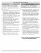
EXAMPLE 2: Boiler Located in Confined Space Asphyxiation, fire hazard. Do not obstruct air openings to combustion area. Follow instructions below, to maintain adequate combustion air. Install outside air intake if you use fireplace or kitchen or bathroom exhaust fan. These devices rob boiler and water heater of combustion air. Provide enough fresh air to assure proper combustion. Fire in the boiler uses oxygen. It must have continuous supply.
B, All Air from Outdoors: Confined space shall be provided with two permanent openings, one commencing within 12 inches of top and commencing within 12 inches of bottom of enclosure. Openings shall communicate directly, or by ducts, with outdoors or spaces (crawl or attic) that freely communicate with outdoors. 1. When directly communicating with outdoors, each opening shall have minimum free area of one square inch per 4,000 Btu per hour of total input rating of all equipment in the enclosure. 2.
, , , Installation of boiler for new heating system, Install all of radiation units (panels, radiators, baseboard, or tubing) and supply and return mains first. After all heating system piping and components have been installed, make final connection of system piping to boiler. It is recommended to mount circulating pump on supply side piping, such that it pumps away from expansion tank. Refer to figures on next pages. Equip hot water boiler installed above radiation level with low water cut off device.
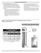
Figure 7 = Bypass Piping Arrangement Diagram > LOW DESIGN SYSTEMS WATER TEMPERATURE > LARGE WATER CONTENT > PIPING ARRANGED FOR "POWER PURGING" AIR OUT OF THE SYSTEM PIPING! REFER TO THIS MANUAL'S SECTION ON "FILLING THE SYSTEM WITH WATER" OPTION #i SYSTEMS | ADJUST THE TWO THROTTLING VALVES TO | MAINTAIN AT LEAST 120 DEGREES FER_NHE_T iN THE BOH_ER RETURN THE THROTTUNG VALP_ES ARE USED FOR BYPASS PIPING, IF REQUIRED 1 THROTTLING AUTOMATIC rILL VALVE SHUTOFF BOILER VALVE CIRCULATOR PUMP V
Figure 8 = System Piping Arrangement > CIRCULATOR AWAY FROM ON Zoning With Zone Valves ON SUPPLY PIPING EXPANSION TANK PUMPS CIRCULATOR CAN ALSO BE INSTALLED RETURN PIPING.
Figure 9 = System Piping Arrangement Zoning > CIRCULATOR ON SUPPLY PIPING AWAY FROM EXPANSION TANK > PIPING ARRANGED FOR"POWER With Circulators PUMPS PURGING" AIR OUT OF SYSTEM PIPINGI REFER TO THIS MANUAL'S SECTION ON "FILLING THE SYSTEM WITH WATER" OPTION #1 B_L_A bK/IN/I FLHW V AL "dE; CHECK VALVE ZOI_@E OIRCUL #_TQR F_E"_ _:_N FROM SYS _EN T_HL AT[ON 'VALVE: gJPPL1 " SYSTD4 iii iiii iiiiii iiiiiiii iii iiiii iiiii iiiiii iiiii iiiii iiiiii iii iiii iiiiii iiiiiiii iii iiiii iiii
Figure > > 10 = System Piping Arrangement DIAPHRAGH EXPANSION OFF THE BOILER TANK Alternate Near Boiler Piping > PER THIS MANUALI "FILLING THE SYSTEM USE OPTION #2 WITH WATER" > THIS PIPING ARRANGEMENT WITH ZONE VALVES OR ZONE CIRCULATORS IN HOUNTED CIRCULATOR ON SUPPLY PIPING AWAY FROM EXPANSION TANK PUMPS F] i TRIll / Ti =If i Ui:;;![II.
Tankless !m Coil Piping Arrangement Boilers may be factorypackaged with tankless heater coil see figure below. Coil provides instantaneous heating of water for domestic use if proper burner and water supply line controls are used. Tankless coils are meant to provide domestic hot water for intermittent draws, not continuous flow. Do not use tankless coil if your water is excessively hard with lime or other deposits which will accumulate inside the coil.
Antifreeze added to boilers must be nontoxic, and must be of type specifically intended for use in closed hydronic heating systems, Under no circumstances should automotive antifreeze be used, Antifreeze used in any boiler may reduce capacity by 10% or more and increase fuel consumption, Tankless coil performance will fall as concentration of antifreeze is increased, Refer to boiler and piping water volumes tables, ½" 82.5 63.5 ¾" 40.0 36.0 1" 23.3 22.2 1 ¼" 15.3 12.8 1 ½" 10.8 9.5 2" 6.
For oil fired boilers for connections to vents or chimneys, vent installations shall be in accordance with applicable provisions of INSTALLATION OF OIL BURNING EQUIPMENT, NFPA31 latest revision, and applicable provisions of local building codes. Fresh air (ventilation) is important to proper Fire Hazard. Maintain minimum vent pipe clearance of 18" from surface of vent to wood and other combustible materials. Failure to comply in death or serious injury.
Figure 12 -Typical Chimney Connection s MINIMUM HEIGHT: MuST SEAT LEAST 3 FT HIGHER THAN HIGHEST PART OF PASSAGE THROUGH ROOE MUST BE AT LEAST 2 FT HIGHER THAN ANY NEIGHBORING OBJECT WITHIN 10 FT. MUST HAVE AN UNOBSTRUCTED TOP OPENING \ MUST AT BE AT LEAST INCHES THICK AND BE - HUST SLOPE UP LEAST I/4, INCH PER KOOT OF HORZZONTALo IN BRAF VANE REGULATOR THIHBLE ALTERNATE POSITIONS
Electrical shock hazard. Turn OFF electrical power supply at service panel before making electrical connections. Failure to do so could result in death or serious injury. Thermostat Install 24 Volt thermostat (not provided) in proper location. Location of thermostat has effect on boiler system operation. Follow instructions included with thermostat. Grounding Permanently ground boiler according to local codes and latest revision of the National Electrical Code.
How A Hot Water System Operates Entire heating system (boiler, piping, and radiation units) is filled with water. As water in the boiler is heated, it is circulated from top of boiler through supply main to radiation units. Cooler water in radiation units flows back through return piping through return main into the boiler. This arrangement provides positive and rapid response to the thermostat. Filling The System With Water OPTION #1 This method utilizes boiler piping as shown in figure on page 6.
Start: Fill entire system with water. Vent all air from system following section for Filling The Boiler. Fuel Units And Oil Lines: o Install oil line(s) to oil burner. o Recommend using heavy wall copper tubing and flared fittings, not compression fittings. All connections and joints must be absolutely airtight. Use an appropriate non=hardening thread sealing compound on the threaded connections, not Teflon tape.
Nozzles And Electrodes: Use proper size, spray angle, and spray pattern nozzle. Refer to recommended nozzle selection charts. To install nozzle, remove nozzle line electrode assembly, if necessary remove retention ring assembly, and install and tighten nozzle. Take care not to damage electrode insulators or bend electrode tips. After installing nozzle, reassemble nozzle line electrode assembly and set electrode tip spacing.
Figure 13 =Burner 4',F5 _8 Adjustments and Settings UW",,/EF/ LiE_ /AA]ASL_ D 41-24S£/}N #, _.._..KEIT AFG Di_4E_SI (V)l/ AI}S lhl_ /AAIAf:>L,L F_EAZ ADjjS"I"F'Et',TS AND '\ ,.
Burn, scald hazard. Do not attempt to start the Locate thermostat Locate thermostat avoid the five feet above the floor on inside wall. to sense average room temperature, burner when excess oil has accumulated, when the unit is full of vapor, or when the combustion chamber is very hot. Concealed pipes Behind You or your installer carefully.
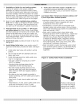
Annually: Recommend flue passages, combustion chamber area (target wall, fire door insulation, durablanket), burner adjustment, control operation, and boiler seals (fire door gasket or silicone seal, cast iron sectional seals, flue collector) be checked once each year by trained Service Technician. Diaphragm Expansion Tank-" Tank may become water logged. Frequent automatic opening of safety relief valve indicates water logging.
Oil Boiler Cleaning: , , Shut off all electrical power to boiler / burner and shut off fuel oil supply. , Remove vent pipe from top of boiler. Inspect pipe and chimney for signs of corrosion and deterioration. Clean out base of chimney. If vent pipe shows any signs of corrosion or deterioration, replace it immediately. If chimney damage or deterioration is discovered, contact a service technician.
These are general instructions for cleaning an oil burner, For specifics, consult burner manufacturer's instructions. Electrical shock hazard. Turn OFF electrical power supply at service panel before making electrical connections. Failure to do so could result in death or serious injury. 1. Verify all electrical power to boiler / burner and fuel supply to burner are shut off. 2. With swing door open, clean any soot accumulations from end of burner and if applicable burner head. 3.
iiiii iiiiii iiiii iiiii iiiiii iiiii iiiii iiiiii iiiii iiiii iiiiii iiiii iiiiii iiiii iiiii iiiiii iiiii iiiii iiiiii iiiii iiiii iiiiii iiiii iiiiii iiiii iiiii iiiiii iiiii iiiii iiiiii iiiii iiiii iiiiii iiiii iiiiii iiiii iiiiii iiiii iiiii iiiiii iiiii iiiii iiiiii iiiii iiiiii iiiii iiiiii iiiii iiiii iiiiii iiiii iiiii iiiiii iiiii iiiii iiiiii iiiii iiiiii iiiii iiiii iiiiii iiiii iiiii iiiiii iiiii iiiii iiiiii iiiii iiiiii iiiii iiiii iiiiii iiiii iiiii iiiiii iiiii iiiii iiiiii iiiii iiiiii ii
m_ c I 0 m_ 0 L_] LIMIT SENSOR BURNER / CONTROL BECKETT 7505 PRIMARY CONTROL iiiiiiiiiiiiiiiiiiiiiiii THERMOSTAT 24 VOLT iiiiiiiiiiiiiiiiiiiiiiii (BY INSTALLER) LOW LIMIT (W/TANKLESS ONLY) it_ L2 0 L2 (WHT) (ORG) (WHT) @ •,_ BLK m _ WHT,,,m m_ it_ IONITER (BLUiWHT) MOTOR _iiii! _iiiii m m LIMIT (BLK) L2 (WriT) VALVE L2 (Vl) (WriT) CAD CELL (YEL!RED) CAD CELL (YEL) 0
iiiiiiiiiiiiiiiiiiiii c iiiiiiiiiiiiiiiiiiiiiii iiiiiiiiiiiiiiiiiiiiiii iiiiiiiiiiiiiiiiiiiiiii iiiiiiiiiiiiiiiiiiiii ' _; o iiiiiiiiiiiiiiiiiiiii iiiiiiiiiiiiiiiiiiiii iiiiiiiiiiiiiiiiiiiii iiiiiiiiiiiiiiiiiiiiiii iiiiiiiiiiiiiiiiiiiiiii iiiiiiiiiiiiiiiiiiiii LIMITSENSOR BURNER ,/ CONTROL RIELLO PRIMARYCONTROL THERMOSTAT 24 VOLT (BY INSTALLER) --] LOW LIMIT (W/TANKLESS = iiiiiiiiiiiiiiiii iiiiiiiiiiiiiiiii Im iiiiiiiiiiiiiiiiiiiiiii •_ iiiiiiiiiiiiiiiiiiiiiii iiiiiiiiiiiiiiiiiiiiiii iiiiiii
HAIN AIR VENT: for down flow systems or diaDhragj:n= _oe exoansion tanks (not provided)_ Before system is filled with water, there is air in pipes and radiation units, Some air will be trapped as system is filled, It is possible to eliminate most of this air through air vents on radiation units, Main air vent will speed and simplify this process, Install main air vent on highest point in supply main when all radiation is below top of boiler, AUTOMATIC FILL VALVE (not Drovided_ For safe, efficient operati
NOTES
DUNKIRK BOILERS 2201 Dwyer Avenue, Utica NY 13501 web site"www,ecrinternational,com