Product Literature Lennox Industries Inc. Dallas, Texas Installation INSTRUCTIONS GWB9 GAS-FIRED, DIRECT VENT, CONDENSING, HOT WATER Boiler Retain These Instructions for Future Reference These instructions must be affixed on or adjacent to the boiler. WARNING Improper installation, adjustment, alteration, service, or maintenance can cause injury or property damage. Refer to this manual. For assistance or additional information consult a qualified installer, service agency, or the gas supplier.
90-50-100 GAS-FIRED BOILER Model No. 90-50 90-75 90-100 These instructions must be affixed on or adjacent to the boiler. ! WARNING Improper installation, adjustment, alteration, service, or maintenance can cause injury or property damage. Refer to this manual. For assistance or additional information consult a qualified installer, service agency, or the gas supplier. ! CAUTION Read all instructions carefully before starting the installation. Save this manual for reference.
Table Of Contents Introduction............................................................................................................................................................ 6 Boiler Ratings & Capacities.................................................................................................................................... 7 Boilers For Use At High Altitude............................................................................................................................
Table Of Contents G. Differential Pressure Air Proving Switch/Blocked Vent Safety Shutoff.................................................................................. 36 H. Draft Inducer................................................................................................................................................................................. 37 I. Circulator Pump..........................................................................................................................
Introduction This appliance is a gas-fired direct vent hot water boiler with cast aluminum boiler sections. A revolutionary cast aluminum heat exchanger means better heat transfer and thermal storage than similarly sized cast iron boilers, which results in higher efficiency. The heating system water absorbs large amounts of heat from the cast aluminum heat exchanger, cooling the flue gases and causing condensation.
Boiler Ratings & Capacities Model TABLE #1 – SEA LEVEL RATINGS – NATURAL AND PROPANE GASES Input ++ Heating Capacity Net I=B=R Rating Shipping Flue Dia. *(MBH) Weight (lbs.) *(MBH) *(MBH) 90-50 50 90-75 75 90-100 100 * 1 MBH = 1,000 Btuh 45 68 90 39 220 59 220 78 220 Btuh = British Thermal Units Per Hour These low pressure gas-fired hot water boilers are design certified by CSA International for use with natural and propane gases.
Boilers For Use At High Altitude The boilers (with the exception of the 90-75 LP product) are factory equipped for operation at altitudes ranging from 0-10,000 feet above sea level. No changes to the factory settings are required for installations from 0-5,000 feet above sea level. For altitudes from 5,000-10,000 feet above sea level the gas manifold pressure will need to be adjusted based upon calorific (Btu) value of supply gas (contact local gas utility or distributor for this value).
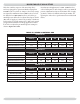
Boilers For Use At High Altitude NOTE: For model 90-75 LP units only at altitudes above 5,000 ft., install 90-75 High Altitude Orifice Kit #550001810*. For all other altitudes use factory installed orifice. Altitude in Ft. Normal Input (MBH) TABLE #2: SERIES 90 PROPANE GAS Series 90-50 Stock Factory Btu Value of LP Gas++ Settings 2300 2350 2400 2450 0-5,000 5,000-10,000 – – – – 50 Manifold Pressure In W.C. 2.5 Orifice 43331095 Altitude in Ft. Normal Input (MBH) Manifold Pressure In W.C.
Rules For Safe Installation And Operation 8. Follow a regular service and maintenance schedule for efficient and safe operation. 1. Read the entire installation manual before beginning the installation. Failure to follow these rules for safe installation and operation and these instructions could cause a malfunction of the boiler and result in death, serious bodily injury, and/or property damage. 9. Keep boiler area clean of debris and free of combustible and flammable materials. 10.
BEFORE INSTALLING THE BOILER feet above finished grade in the area of the venting, including but not limited to decks and porches, the following requirements shall be satisfied: 5. Product-approved vent/air-intake: a product-approved vent terminal must be used and, if applicable, a productapproved air intake must be used. Installation shall be in strict compliance with the manufacturer’s instructions. 1.
BEFORE INSTALLING THE BOILER 11. Equipment shall be installed in a location which facilitates the operation of venting and combustion air intake piping systems as described in this manual. D. Locating The Boiler 7. Select a location which is level, central to the piping systems served and as close to the vent and air intake terminals as possible. 12. Advise owner of boiler to keep venting and combustion air intake passages free of obstructions.
BEFORE INSTALLING THE BOILER ! CAUTION F. Condensate Drain Requirements Condensate drain line to be pitched down to floor drain at a minimum of ¼” per foot. An external condensate pump (not furnished) may be used if floor drain is not available. The condensate pump must be designed for flue gas condensate application. Keep boiler area clean of debris and free of flamable and combustible materials, vapors and liquids.
BEFORE INSTALLING THE BOILER on clothes dryer and any appliance not connected to the common venting system. Turn on any exhaust fans, such as range hoods and bathroom exhaust, so they will operate at maximum speed. Close fire dampers. G. Foundation Requirements Boiler must be placed on level surface. Boiler is NOT to be installed on carpeting. 4. Place in operation the appliance being inspected. Follow the lighting instructions. Adjust thermostat so appliances will operate continuously.
Placing The Boiler The boiler should be placed to provide the most direct connections to the combustion air, vent and system piping as possible. Place crated boiler as close to selected location as possible and uncrate boiler. The uncrated boiler may be moved into position with an appliance dolly or 2-wheel hand truck. The dolly or hand truck should be inserted under the left hand side of the boiler. It is possible to slide the boiler for a short distance on a smooth floor or surface.
Near Boiler Piping Figure 2 - Single Zone Boiler Piping 15
Near Boiler Piping Figure 3 - Multi-zone Boiler Piping With Zone Valves 16
Near Boiler Piping Figure 4 - Multi-Zone Boiler Piping With Circulators NOTE: When zoning with circulators, the furnished circulator pump should be used as one of the zone pumps. Each stripped end of the electrical wires for the circulator pump inside the junction box should be taped or wire nutted to prevent short circuits. Unplug the circulator pump wiring at the integrated boiler control.
Near Boiler Piping Figure 5 - Single Zone Boiler Piping B. Pressure Relief Valve The boiler is furnished with a factory installed relief valve in the top of the boiler. Provide ¾” piping from the supplied relief valve to a local floor drain, but leave an air gap between piping and drain. No shutoff of any description shall be placed between safety relief valve and the boiler, or on the discharge pipes between such safety valve and the atmosphere.
Near Boiler Piping Figure 6 - Diaphragm Type Expansion Tank Piping 19
Near Boiler Piping Figure 7 - Conventional (closed type) Expansion Tank Piping 20
Near Boiler Piping Figure 8 - Condensate Drain Piping The ½” diameter schedule 40 PVC or CPVC condensate drain and pipe fittings must conform to ANSI standards and ASTM D 1785 or D2846. Schedule 40 PVC or CPVC cement and primer must conform to ASTM D2564 or F493. In Canada, use CSA or ULC certified schedule 40 PVC or CPVC drain pipe cement. D. Condensate Drain Piping The condensate trap is built into the boiler, an external trap is not required and should NOT be used.
Near Boiler Piping E. Filling Condensate Trap With Water On The Initial Start Up The Condensate Trap Must Be Manually Filled With Water. F. Chilled Water Piping The boiler, when used in connection with a refrigeration system, must be installed so the chiller medium is piped in parallel with the boiler with appropriate valves to prevent the chilled medium from entering the boiler.
Combustion Air and Vent Pipe 3. Combustion air and vent piping connections on boiler are sized for 2” pipe. Any pipe size change (to 3”) must be made outside of the boiler casing in a vertical run of pipe to allow for proper drainage of vent condensate. Due to potential for flue gas temperatures over 155°F, the first five (5) feet of vent pipe must be CPVC, the remaining vent pipe can be PVC. If any elbows are employed within the first 5 feet of vent, they must be CPVC too.
Combustion Air and Vent Pipe 4.
Combustion Air and Vent Pipe snow may cause the boiler to shut down if the vent becomes obstructed. 6. Consideration for the following should be used when determining an appropriate location for termination of combustion air and vent piping. •Under certain conditions, flue gas will condense, forming moisture, and may be corrosive. In such cases, steps should be taken to prevent building materials at the vent from being damaged by exhaust of flue gas. 7.
Combustion Air and Vent Pipe Figure 10 - Side Wall Vent / Intake terminations Less Than 12” Clearance 12” Or More Clearance 26
Combustion Air and Vent Pipe Figure 11 - Combustion Air and Vent Piping 27
Combustion Air and Vent Pipe B. Installation 1. Attach combustion air intake piping to supplied Fernco 2” coupling on mixer. Attach vent piping to furnished 2” CPVC vent tee on draft inducer outlet. 8. While cement is still wet, insert pipe into socket with ¼ turn twist. Be sure pipe is fully inserted into fitting socket. 9. Wipe excess cement from joint. A continuous bead of cement will be visible around perimeter of a properly made joint. NOTE: All pipe joints are to be water tight. 2.
Gas Supply Piping B. Connecting The Gas Piping Refer to Figure #12 (on following page) for the general layout at the boiler. It shows the basic fittings you will need. The gas line enters the boiler from the right side jacket panel. The boiler may receive the gas supply pipe through the left side, or rear jacket panel by relocating the gas valve connector and pipe assembly. The boiler is equipped with a ½” NPT connection on the gas valve for supply piping. The following rules apply: 8. 8.
Gas Supply Piping Figure 12 - Gas Piping Electrical Wiring box and power supply connection points. Connect black (hot) lead from the power supply to either of the unused brass screws on the service switch. Connect the white (neutral) lead from the power supply to the white screw on the service switch. Connect the green (ground) lead from the power supply to the ground (green) screw on the service switch.
Electrical Wiring B. Install Your Thermostat The thermostat location has an important effect on the operation of your boiler system. BE SURE TO FOLLOW THE INSTRUCTIONS INCLUDED WITH YOUR THERMOSTAT. ! CAUTION LABEL ALL WIRES PRIOR TO DISCONNECTION WHEN SERVICING CONTROLS. WIRING ERRORS CAN CAUSE IMPROPER AND DANGEROUS OPERATION. VERIFY PROPER OPERATION AFTER SERVICING. Locate the thermostat about five feet above the floor on an inside wall.
Electrical Wiring Figure 13 - Field Wiring Connections 32
NEUTRAL GRIUND HOT 1 120 VAC 60 HZ 1Ø 24V THERMOSTAT R W 3 1 120 VAC 4 5 VAC Y 24 Y 3 MV MV * CIRCULATOR PUMP W BK PUR PUR CONTROL TRANSFORMER AT14081297 CN9 2 GAS VALVE HI LIMIT AQUASTAT CONTROL CASTING TEMPERATURE SAFETY SWITCH (MANUAL RESET) W V IGNITER CN12 2 1 DRAFT INDUCER CN10 HOT SURFACE IGNITER DRAFT INDUCER 2 1 DIFFERRENTIAL AIR PRESSURE SWITCH (N.O.
Electrical Wiring Figure 15 - E - Ladder Wiring Diagram 120 VOLT POWER SUPPLY 1 L1 L2 HOT WHT BLK ON/OFF SWITCH * P7-1 2K1 P4-3 P4-1 1K1 P10-1 P5-1 CIRCULATOR MOTOR P6-1 HOT SURFACE IGNITER P12-1 P1-1 3 VAC 1 24 VAC 5 CASTING TEMPERATURE SAFETY SWITCH (MANUAL RESET) 1 1 P3-5 R W P3-7 THERMOSTAT P2-2 P9-3 P3-1 DIFFERENTIAL AIR PRESSURE SWITCH MV P9-2 P3-2 INDICATOR LIGHTS POWER PURGE IGNITER VALVE FLAME P3-3 P3-6 BLOWER TEMPERATURE SAFETY SWITCH P3-4 MV MICROPROCESSOR ELECTR
Controls and Accessories and may be set anywhere between 100 °F and 200 °F. The field setpoint adjustment for each installation depends on heating system requirements. The aquastat automatically resets when the boiler water temperature decreases (5-30 °F adjustable differential). The differential can be adjusted with the (white) Differential Adjustment Wheel on the aquastat and gives the flexibility for boiler operation. The larger the differential, the longer the run cycle of the boiler.
Controls and Accessories adequate combustion air flow or flue gas flow. The IBC will be automatically reset after fifteen (15) minutes or can be manually reset from lockout by (a) removing and reestablishing the thermostat call for heat or (b) by turning the service switch off and back on again. If the boiler cannot be restored to normal operating conditions by resetting the control, contact a quallified service agency to check the heat exchanger flue-ways for blockage. K. A.S.M.E.
Water Treatment & Freeze Protection When filling the boiler water is the preferred heating solution. Most potable water supplies may be used to charge and re-fill provided the chlorine and chloride ions levels are less than 100 ppm. Piping Recommendations System leaks may not always be visible. An unseen system leak will become obvious if boiler pressure decreases when make up valve is closed.
WATER TREATMENT & FREEZE PROTECTION Cleaning the Hydronic System IMPORTANT: Do not mix different manufacturers’ products. Doing so will void the warranty of the boiler. Freeze Protection Aluminum Safe Antifreeze, Treatments and Additive Guidelines: Consideration MUST be given to cleaning the heating system, particularly in retrofit situations where a new boiler with an aluminum heat exchanger is being installed in an existing piping system.
XII - Water Treatment & Freeze Protection Recommended Aluminum Antifreeze Recommended Products & Inhibitor Suppliers Interstate Chemical 2797 Freedland Road P.O. Box 1600 Hermitage, PA 16148-0600 www.interstatechemical.com Tel: 800-422-2436 Intercool NFP-30,40,50 AA Intercool RPH-15* Fax: 724-981-8383 Noble Company PO Box 350 Grand Haven, MI 49417 www.noblecompany.com Tel: 800-878-5788 Noburst AL Antifreeze Fax: 800-272-1519 Rhomar Water Management, Inc.
Start Up zone. Open the purge valve on the first zone. Feed water will fill the zone, pushing air out the purge valve. Close the purge valve when the water runs air free. Close the zone service valve. A – Filling Boiler With Water And Purging Air For Systems With Diaphragm Type Expansion Tanks Refer to the appropriate diagrams in Section VII, “Near Boiler Piping,” for more information. 1. Close all zone service valves on the supply and return piping. Open the feed valve and fill boiler with water.
Start Up C - Placing Boiler In Operation ! WARNING If you do not follow these instructions exactly, a fire or explosion may result causing property damage, personal injury or loss of life A. This appliance is equipped with an ignition device which automatically lights the pilot. Do not try to light the pilot by hand. •If you cannot reach your gas supplier, call the fire department. C. Use only your hand to move the system control switch. Never use tools.
Check Out Procedure and Adjustment Figure 16 - Indicator Lamps A. Verify Proper Sequence Of Operation The sequence can be followed via the diagnostic indicator lamps on the Honeywell S9301A integrated boiler control in Figure #16. This is the normal sequence of operation. A more detailed sequence of operation containing potential faults can be found in the service hints section. SEQUENCE OF OPERATION “DIAGNOSTIC INDICATOR LAMPS” “Power ON, boiler standing by.
Check Out Procedure and Adjustment SEQUENCE OF OPERATION “DIAGNOSTIC INDICATOR LAMPS” After pre purge, Lamp B goes out and Lamp C illuminates, indicating the hot surface igniter is powered for the 20 second igniter warm-up period. The bright yellow orange glow of the hot surface igniter can be observed through the observation port in the front boiler section just above the igniter. A. B. C. l D. m E.
Check Out Procedure and Adjustment 5. Turn off all other gas appliances, extinguishing standing pilots where applicable. F. Test High Limit Control And Adjust While burner is operating, move indicator on high limit control below actual boiler water temperature. Burner should go off while circulator continues to operate. Raise limit setting above boiler water temperature and burner should reignite after pre purge and igniter warm-up period.
Check Out Procedure and Adjustment IV. Measure new input rate (cover screw must be installed). Repeat steps I.-IV until the input rate is within +/-2% of the nameplate input rating. V. If the actual input rate can not be set to within 2% of the correct input rating by adjusting manifold pressure, a change in gas orifice size is required. Consult the boiler manufacturer for information on correct orifice sizing.
Check Out Procedure and Adjustment Figure 17 - Manifold Pressure Measurement Detail The following steps and diagram indicate the location of the connection points required to measure the manifold pressure. The manifold pressure may be measured using a U-Tube Manometer or a Differential Pressure Gauge. The diagram shows the connection of both measuring devices. Only ONE DEVICE IS REQUIRED to measure the manifold pressure. Remove the plug.
INSTALLATION AND CHECK-OUT CERTIFICATE Boiler Model Serial # Date Installed___________ Measured BTU/HR input____________ Installation instructions have been followed Checkout procedure and adjustments performed Maintenance and Service issues reviewed with owner/ maintenance person Installation booklet affixed on or adjacent to boiler Installer (Company) Address Phone Installer’s Name Signature 47
Maintanance And Cleaning Maintenance as outlined below can be performed by the owner unless otherwise noted. Insure that there are no leaks. Use RTV silicone rubber adhesive sealant (available in caulking gun tubes) rated for at least 400° F to replace or repair seals in locations where original seals have deteriorated. The acidic nature of flue gasses condensing on the aluminum boiler sections will cause the formation of aluminum oxide.
MAINTANANCE AND CLEANING Monthly During Heating Season 1. 1. Remove jacket front and top panels and check for piping leaks around relief valve and other fittings. If found, contact a qualified service agency to repair. DO NOT use stop leak compounds. Annual Examination And Cleaning Of Boiler Components The following service procedures must be performed only by a qualified service agency. Boiler owner should not attempt these procedures. 2. 2. Test relief valve.
MAINTANANCE AND CLEANING C. Remove the condensate trap and run cold water through the condensate lines to thoroughly flush out any sediment or debris in the lines. H. After rinsing, remove any remaining loosened sediment using a shop vacuum with a snorkel attachment. I. Inspect burner for any foreign matter in the flame ports or inside the burner. Any foreign matter should be removed by blowing with compressed air or vacuuming. D.
Detailed Sequence Of Operation Service Hints POWER ON STAND BY THERMOSTAT CALLS FOR HEAT IF MAIN BURNER DOES NOT PROVE FLAME IN 3 TRIALS, CONTROL LOCKOUT. VALVE/FLAME LIGHT BLINKS. MANUAL RESET IS REQUIRED OR CONTROL WILL AUTOMATICALLY RESET AFTER 1 HOUR. THIS PROBLEM IS A RESULT OF NOT ESTABLISHING A FLAME SIGNAL. CIRCULATOR ENERGIZES THRU 2K1 CONTACTS IBC SELFCHECK OF INTERNAL CIRCUITRY 1-2 SEC CONTROL WILL ATTEMPT 2 ADDITTIONAL IGNITION SEQUENCES. STARTING WITH PREPURGE. IBC CHECKS N.O.
DETAILED SEQUENCE OF OPERATION DRAFT INDUCER TEMPERATURE SAFETY SWITCH CASTING TEMPERATURE SAFETY SWITCH IF DRAFT INDUCER TEMPERATURE REACHES TEMPERATURE SAFETY SWITCH SETPOINT, SAFETY SWITCH CONTACTS OPEN IMMEDIATELY CLOSING GAS VALVE (LIGHT GOES OUT) IF BURNER OPERATES WHEN BOILER HAS NO WATER, ALUMINUM BOILER SECTIONS HEAT UP RAPIDLY. CASTING TEMERATURE SAFETY SWITCH CONTACS WILL OPEN BREAKING 24 VOLT POWER TO IBC. POWER INDICATOR LIGHT GOES OUT. REQUIRES MANUAL RESET TO RE-CLOSE CAONTACTS.
DETAILED SEQUENCE OF OPERATION 53
Troubleshooting ! WARNING Fire, explosion or shock hazard may cause property damage, severe injury or death. Do not attempt to modify the physical or electrical characteristics of this boiler in any way. Important 1. In a reset from lockout condition, all electrical meter readings at the gas control valve (24 vac) must be taken within the trial for ignition period. 2. If any component does not function properly, make sure it is correctly installed and wired before replacing it. 3.
TROUBLESHOOTING System Status THE INDICATOR LIGHTS TRACK THE OPERATING SEQUENCE. IF THE SYSTEM LOCKS OUT, THE LIGHTS INDICATE THE POINT IN THE SEQUENCE OF OPERATION WHERE LOCKOUT OCCURS. IF THIS TABLE DOES NOT READILY PROVIDE THE REASON FOR BOILER MALFUNCTION OR NON-OPERATION, REFER LIGHT POWER STATUS INDICATES ON IBC IS ENERGIZED THROUGH 24 VOLT TRANSFORMER. OFF IBC IS NOT ENERGIZED. BLINKING ON IBC RECEIVES MORE THAN 40 VAC IBC IS ENERGIZING THE DRAFT INDUCER AND AIR FLOW IS PROVEN.
TROUBLESHOOTING TROUBLESHOOTING CHART 1 ! WARNING Electrical shock hazard may cause Serious injury or death. The following procedures may expose you to dangerous line voltage. Use caution to avoid touching live electrical contacts. Service must be performed by a trained, experienced service technician. What to do if you smell gas: • Do not try to light any appliance • Do not touch any electrical switch; do not use any phone in your builidng.
TROUBLESHOOTING TROUBLESHOOTING CHART 2 ! " # " " " " ! " # " ! " "
TROUBLESHOOTING TROUBLESHOOTING CHART 3 " % !" "! $ "% " ! " " & ! & ! $ " % ! % !! % " % & ! % !!# !% " " "! # " & ! % "! # " #" ! & !!# !% " " "! " ! " % !# " ! ! " $ " "
TROUBLESHOOTING TROUBLESHOOTING CHART 4 CHART 3 yES IGNITER/SENSOR WARMS UP AND GLOWS yELLOW/ORANGE DURING 20 SECOND WARM UP NO CHECk FOR 120 VAC BETWEEN TERMINALS 1 AND 2 AT CONNECTOR CN1 ON IBC (DURING IGNITER WARM UP) yES NO yES CHECk FOR 120 VAC AT IGNITER/SENSOR LEADS ON WIRING HARNESS (DURING IGNITER WARM UP) NO yES AFTER 20 SECOND IGNITER WARM UP, GAS VALVE IS ENERGIzED ValVe liGht is on 2 SECONDS LATER POWER IS REMOVED FROM IGNITER/SENSOR iGniteR liGht is off DOES MAIN BURNER LIGHT? REPLACE
TROUBLESHOOTING TROUBLESHOOTING CHART 5 #% * $ #% * $ ! $$ * )%&# % $ $ ( $%# $ ' ' # # $ $ # $ $ ' %&# ' ' ## % $ + $ # ! # ! #%$ # # ! $ $ $&# % &$ ## % $ ' %&# ' ' $ + * $ ! $$ * %&# % # & ! $$ $ # ! # % # & ! $$ $ # # & ! $$ $ ! # % $%#& % $ * $
TROUBLESHOOTING TROUBLESHOOTING CHART 6 CHART 5 yES CHART 5 NO #2 CHART 5 NO #3 REPLACE GAS CONTROL. yES CHECk GAS ORFICICE SIzE. IS GAS ORIFICE SIzE CORRECT. CHECk REPAIR PARTS LIST FOR CORRECT SIzE. IS GAS ORIFICE CLEAR OF BLOCkAGE. RUNS FOR 25-50 SECONDS, THEN TURNS OFF. CHECk FIRING RATE OF UNIT. IS UNIT FIRING AT THE CORRECT RATE? yES NO DOES THE UNIT USE LP GAS. NO ADJUST RATE AS DESCRIBED IN THE CHECk OUT PROCEDURE AND ADJUSTMENT SECTION OF THE MANUAL.
Differential Air Pressure Switch Check What Is System Status? The following steps and diagram indicate the locations of the connection points required to check the differential air pressure. The differential air pressure switch is a safety device which will prevent the boiler from firing if there is an air intake, boiler heat exchanger or vent blockage. Turn off service switch, or lower thermostat setting. Remove vinyl caps from Tee and 4-way connector.
REPAIR PARTS UB90-50-100 GAS-FIRED, DIRECT VENT, CONDENSING, HOT WATER Boiler Model No.
Repair Parts A.
Repair Parts JACKET AND BASE ASSEMBLY KEY # DESCRIPTION QUANTITY ITEM NUMBER 1 FRONT PANEL 1 750001020 2 RIGHT PANEL 1 750001021 3 LEFT PANEL 1 750001022 4 BACK PANEL 1 750001023 5 TOP PANEL 1 750001024 6 BASE 1 750001025 7 CONTROL PANEL 1 650001026 8 AT140B1016 TRANSFORMER 24 VAC 1 550001339 ---- ---- 10 9 UT 1013-10 INTEGRATED BOILER CONTROL ---- 1 14662803 11 CO-2366 GLIDE 4 14631091 12 HEYCO OCB-1500 BUSHING 1 14631120 13 RACO 232 4´4´2 BOX 1 14631
Repair Parts B. Condensate Drain Trap Assembly Connect to the drain port at the bottom of boiler 3 Connect to the drain port at the exhauster 1 1 7 4 8 2 KEY # 1 2 3 4 5 6 7 8 DESCRIPTION 59019 ½”IDx1/8” THK VINYL TUBING 57134 ¾” SNAP GRIP CLAMP 62067 ½”ID HOSE TEE 62017 ½”NPTx ½”ID TUBE STRAIGHT ½” PVC COUPLING, SCH 80 ½”´4” PVC NIPPLE, SCH 80 TEE PVC ½”SLIP x ½”SLIP x ½”NPT FEMALE S. S.
Repair Parts C.
Repair Parts D.
Repair Parts BOILER BLOCK AND PIPING ASSEMBLY KEY # ITEM NUMBER DESCRIPTION QUANTITY 1 41800650 KIT BLOCK REPL Q90-100 (INCLUDES #2 THRU #19) 1 2 14607044 NPL,1-1/4X2-1/2,BI,STD 2 3 14607201 NPL,3/4X2,BI,STD 1 4 14619002 OBSERVATION GLASS, 3/4” 1 5 14631000 SWITCH CASTING TEMP Q90 36T26-42930 300 1 6 14631004 ADAPTER, SIGHT GLASS 1 7 14631005 FITTING, 125HBL-4-2 1/8”X1/4”BR.
Repair Parts E.
Repair Parts MIXER AND AIR PRESSURE SWITCH ASSEMBLY KEY # 1 DESCRIPTION BURNER GASKET QUANTITY ITEM NUMBER 1 14631023 2A BURNER Kit, 50 &100 NAT/LP, 0’-10,000’ (Contains: 1, 2, 3, 7, 10, 11, 12 & 29) 1 550001811 2B BURNER Kit, 75 NAT, 0’-10,000’ (Contains: 1, 2, 3, 7, 10, 11, 12 & 29) 1 550001811 2C BURNER Kit, 75 LP, 0’- 5,000’ (Contains: 1, 2, 3, 7, 10, 11, 12 & 29) 1 550001811 2D BURNER Kit, 75 LP, 5,000’-10,000’ (Contains:1, 2, 3, 7, 10, 11, 12, 27F & 29) 1 550001812 MIXER GASKET
Product Literature Lennox Industries Inc.