
Installation manual

25
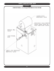
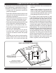
8" MINIMUM
VERTICAL SEPARATION
BETWEEN COMBUSTION
AIR INTAKE AND VENT
MAINTAIN 12" MINIMUM
CLEARANCE ABOVE HIGHEST
ANTICIPATED SNOW LEVEL
3'' MAXIMUM
SEPARATION
15'' MAXIMUM
COMBUSTION
AIR
12''
MIMIMUM
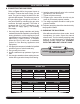
6. Consideration for the following should be used
when determining an appropriate location for
termination of combustion air and vent piping.
• Comply with all clearances required as
stated in paragraph 7.
•
Termination should be positioned where vent
vapors will not damage plants/shrubs or air
conditioning equipment.
•
Termination should be positioned so that it
will not be effected by wind eddy, air born
leaves, snow, or recirculated flue gases.
• Termination should be positioned where it will
not be subjected to potential damage by
foreign objects, such as stones, balls, etc..
•
Termination should be positioned where vent
vapors are not objectionable.
•
Put vent on a wall away from the prevail-
i
ng winter wind. Locate or guard the vent
to prevent accidental contact with people
or pets.
• Terminate the vent above normal snowline.
Avoid locations where snow may drift and
block the vent. Ice or snow may cause the
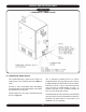
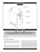
COMBUSTION AIR AND VENT PIPE
boiler to shut down if the vent becomes ob-
structed.
• Under certain conditions, flue gas will con-
dense,
forming moisture, and may be cor-
rosive. In such cases, steps should be taken
to prevent building materials at the vent from
being damaged by exhaust of flue gas.
7. The venting system shall terminate at least
3 feet above any forced air inlet (except the
boiler’s combustion air inlet) within 10 feet.
The venting system shall terminate at least 12
inches from any air opening into any building.
The bottom of the vent shall be located at least
12 inches above grade. Termination of the vent
shall be not less than 7 feet above an adjacent
public walkway. The vent terminal shall not be
installed closer than 3 feet from the inside cor-
n
er of an L shaped structure. Termination of the
vent should be kept at least 3 feet away from
vegetation. The venting system shall terminate
at least 4 feet horizontally from, and in no case
above or below, unless a 4 foot horizontal dis-
tance is maintained, from electric meters, gas
meters, regulators, and relief equipment.
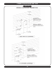
ROOF VENT/INTAKE TERMINATIONS
Figure #9