ARTESIAN 220 & 340 Instantaneous Indirect Water Heater By Dunkirk Boilers • INSTALLATION AND OPERATING INSTRUCTIONS • ENGINEERING MANUAL
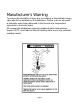
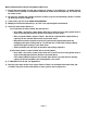
Manufacturer's Warning To reduce the possibility of injury due to scalding, a thermostatic mixing valve should be installed on all installations. Failure to do so will result in domestic water being delivered to the faucets at a temperature equivalent to the boiler water. All commercial installations requiring sustained water temperatures beyond 120°F, must label all fixtures alerting water users of a potential scalding hazard.
CONTENTS pg I. Product Description................................................................................................ 4 II. Specifications ......................................................................................................... 4 III. Sizing A Water Heater For Installation................................................................ 7 Method A - Quick Residential............................................................................. 8 Method B - Detailed Residential.
I. Product Description The Indirect water heater is designed to generate domestic hot water in conjunction with a hot water boiler using forced boiler water circulation. This indirect water heater consists of a plain steel tank in which three smooth copper coils are located. The tank surrounded by 2" of Poly - urethane foam insulation, which is surrounded by an enamel coated plain steel jacket. The boiler water pumps through the tank and heats the domestic water in the coils.
Page 5
Page 6
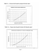
Ill. Sizing The Hot Water Heater For Installation IMPORTANT The following procedures are used to size indirect water heaters based on the amount of hot water required during a given hour. In doing so, it is assumed that this demand will be spread out over the course of the entire hour. THESE SIZING PROCEDURES ARE PROVIDED AS A GUIDE TO ASSIST THE PROFESSIONAL CONTRACTOR IN SIZING THE WATER HEATER.
Method A: Quick Residential Sizing Method Table 4 shows some typical structures under which many single residence applications can be classified. This procedure will provide satisfactory results most of the time. Where greater accuracy is desired, use Method B. 1) Find the description that best fits the job and select the Water heater called for. Also, note the required boiler output under column (F).
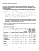
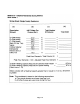
Method B Detailed Residential Sizing Method Directions 1) Record the total number of each type to fixture in column (c) of worksheet 1. A shower head is installed over a bathtub, count both the bathtub and shower head although only one fixture will be used at a time. 2) For each line, multiply the quantity entered in column (c) by the corresponding number in column (b). Enter the result in column (d). 3) Total column (d). This is the PEAK HOUR DEMAND 4) Multiply the Peak Hour Demand by 1.20.
Page 10
Method B - Detailed Residential Sizing Sample Calculations Example 1 A water heater is to be installed with a new boiler. The residence has the following fixtures: Bath #1 Bath #2 3 GPM Shower Head Vanity 30 Gal.
Page 12
IMPORTANT Do not attempt to use Method C to size a single-family residence. Method C: Commercial Sizing Method Directions 1) Table 5 and 6 show demands for various fixtures found in commercial buildings in gallons per hour. To determine the hot water requirements of the building: a) Using Worksheet 2, determine and record the total number of each type of fixture in the building under Column (2) b) Use Tables 5 and 6 to find the number of gallons of 140°F water used per hour per fixture.
b) If the water heater is to be installed with an existing boiler, go to table 1 and select a water heater which has a 140°F first hour rating greater than or equal to the adjusted probable maximum demand calculated in1g. Note the boiler's gross output required to achieve the selected water heater's first hour ratings. If it is more than the gross output of the existing boiler, the existing boiler is too small to provide the proper input to the water heater.
Page 15
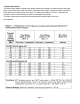
Method C - Commercial Sizing Sample Calculation Example 2 This application is for a motel with 20 rooms. Each of these rooms has the following fixtures: (1) Vanity, (1) Shower and (1) Bath In addition, 5 rooms have an additional vanity. Also, there is a utility sink used by the staff for cleaning and a laundry with two machines Solution: Use Table 5 and the fixture count to complete the example worksheet in figure 3 (on next page).
Page 17
Page 18
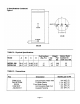
IV. BEFORE STARTING INSTALLATION Table 7: Water Chemistry Requirements 1) Make sure that the planned installation is Water used in the water heater must have in accordance with all local codes. characteristics falling within the following limits: 2) Be certain the domestic water supply to the tank Characteristic Min. Max. fall within the limits shown in Table 7. Where pH 6.0 8.0 questions exist as to the composition of the Dissolved Chlorine (PPM) 0.0 100.
V. Piping IMPORTANT All First Hour Ratings shown in this manual are based on the, minimum boiler water, flow rates shown in Table 1. Read this section for information on sizing piping and circulators for the water heater zone. Zone Design In designing the water heater zone piping system, the following points should be considered: 1) Circulator or Zone Valve Zoning? - Circulator zones are usually a better choice.
3-Way Zone Valve System This system offers a simple method of prioritizing the tank (Diverting all boiler output to the tank when the tank thermostat calls for heat). In this system, a 3-way zone valve is used which has a common port, a "normally open" port, and a "normally closed" port. The zone valve motor is wired to be energized by the water heater thermostat (see Part VII for wiring information). The common side of the zone valve is connected to the boiler.
Page 22
Page 23
Page 24
Page 25
Page 26
Page 27
2) Domestic Water Side Piping Figure 10 shows typical domestic water piping for a water heater. All components except the aquastat are provided by the installer. The function of the components shown are as follows: a) Control (required) - This control is provided by Dunkirk and must be installed in the location indicated. It is imperative that the bulb of the control is "bottomed out" in the control well. b) Shut-off valves (recommended) - use to isolate the tank for servicing.
Domestic Water Piping for Distant Fixtures in some cases, the furthest fixture may be quite distant from the water heater. In such an installation, there will be a slight delay before hot water reaches these distant fixtures. Even if all the fixtures are relatively close to the water heater, the building owner may want hot water at all fixtures as soon as they are opened. Figure 12 illustrates a solution to this problem.
Page 30
Page 31
Page 32
VII. Wiring The following applies to all wiring: 1) Wiring must be done in accordance with all codes. In the absence of any codes, the system must be wired in accordance with the National Electric Code (ANSI/NFPA 70-latest revision). 2) The entire system (boiler controls, water heater and heating zone controls) must be on its own circuit. The current rating of this circuit will depend on the total number and size for loads in the system. However, it should in no case be less than 15 AMPS.
Zone Valves (2 Way Priority) Figure 17 shows a connections diagram for a priority zone system using Honeywell V8043F motorized valves. An R8285B relay is used which is equipped with its own transformer and a set of D. P. D.T contacts. The water heater control is connected to terminals R and G on the R8285B so when the water heater control calls for heat, the relay coil is energized. One side of the transformer is connected to the common contact.
Page 35
Page 36
Page 37
Page 38
Page 39
VIII Start up and Check out IMPORTANT IDENTIFY ANY LEAKS, BY TESTING, BEFORE PROCEEDING FURTHER. WARNING NEVER ATTEMPT TO FILL A HOT BOILER. 1) Be sure to purge all air from water heater and ancillary piping. 2) Be sure that all electrical wiring has been done according to the local codes. 3) Verify that all zone valves or circulators operate properly when their thermostats call for heat. Allow the zones to operate long enough to purge any remaining air.